
Apparatus and method for short circuit defect testing

A short-circuit defect and testing device technology, which is applied in semiconductor/solid-state device testing/measurement, circuits, electrical components, etc., can solve problems such as structural damage, structural failure not found, and test structure damage

Inactive Publication Date: 2012-04-11
SEMICON MFG INT (SHANGHAI) CORP +1
View PDF2 Cites 16 Cited by
  • Summary
  • Abstract
  • Description
  • Claims
  • Application Information

AI Technical Summary

Problems solved by technology

The problem is that during the electrical analysis (EFA) process, due to the excessive pressure applied to the short-circuit defect test device, the test structure is damaged, causing human factors to damage the structure during the analysis, and the real cause of the structural failure cannot be found.

Method used


Image

  • Apparatus and method for short circuit defect testing
  • Apparatus and method for short circuit defect testing
  • Apparatus and method for short circuit defect testing

Examples


Embodiment Construction

[0026] In order to make the object, technical solution, and advantages of the present invention clearer, the present invention will be further described in detail below with reference to the accompanying drawings and examples.

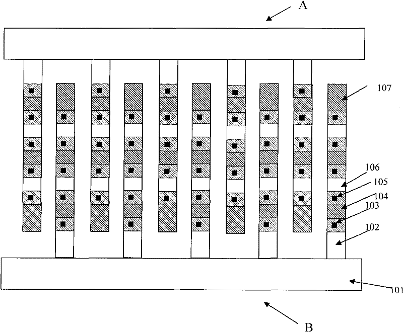
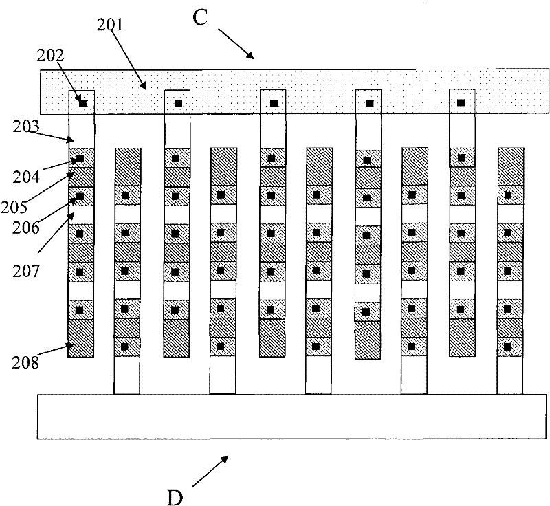
[0027] figure 2 It is a schematic diagram of a short-circuit defect testing device proposed by an embodiment of the present invention. There are multiple conductive layers in the wafer from bottom to top, which are called the first conductive layer, the second conductive layer, the third conductive layer...the Nth conductive layer, and the adjacent conductive layers are separated by an insulating medium. Layers are separated. The short-circuit defect testing device is located in the nth conductive layer, the n+1th conductive layer and the n+2th conductive layer in the wafer, n and N are both natural numbers, and n≤N-2. figure 2 shows the nth conductive layer in the chip, the n+1th conductive layer located on the nth conductive layer, and the n+2th ...


PUM


Abstract

The invention provides an apparatus for short circuit testing. The apparatus comprises a first comb structure body and a second comb structure body. The first comb structure body is formed by a plurality of first short conductor wire chains that are parallel to each other. The second comb structure body is formed by a second conductor wire and a plurality of short conductor wire chains that are vertical to the second conductor wire and are parallel to each other. One ends of all the second conductor wire chains are directly connected with the second conductor wire, wherein the one ends of all the second conductor wire chains are far away from the first short conductor wire chains. And the first short conductor wire chains and the second short conductor wire chains are arranged at intervals. In addition, the invention also provides a method for short circuit defect testing. According to a technical scheme of the invention, a short circuit defect breakdown point position can be accurately localized based on a comparative analysis of passive voltages.

Description

technical field [0001] The invention relates to the technical field of semiconductor integrated circuit manufacturing, in particular to a short-circuit defect testing device and method. Background technique [0002] At present, in the process of manufacturing a wafer (wafer) in a semiconductor integrated circuit (IC) process, the connection between the semiconductor devices fabricated on the wafer is realized through metal interconnection, and the metal interconnection mainly uses metal wiring as a conductive medium. However, the metal interconnection short defect is one of the main failure modes in the IC process, which has a great impact on the wafer yield. Therefore, monitoring and failure analysis of short-circuit defects in metal wiring can promote the improvement of IC technology and increase the yield of wafers. In the prior art, a failure analysis test is designed for the short-circuit defect of the metal wiring. [0003] With the advancement of IC technology, the ...

Claims


Application Information

Patent Timeline
Patent Type & Authority Applications(China)
IPC IPC(8): H01L23/544H01L21/66
Inventor 梁山安务林凤郭强
Owner SEMICON MFG INT (SHANGHAI) CORP
Learn More