
Manufacturing method and product of power connector with wires

A power connector and manufacturing method technology, which is applied in the manufacturing of contacts, circuit/collector parts, contact boxes/bases, etc., can solve the problems of high manufacturing cost, multiple quality of stations, and difficult control.

Inactive Publication Date: 2012-03-28
SHENZHEN ZHITAI ELECTRONICS
View PDF4 Cites 7 Cited by
  • Summary
  • Abstract
  • Description
  • Claims
  • Application Information

AI Technical Summary

Problems solved by technology

[0021] The above structure connector ( Figure 18 , Figure 19 ) needs to go through many assembly processes such as injection molding, turning, stamping, assembly, threading, welding, and heat shrinkable sleeves. The process is complicated, the quality of multiple stations is difficult to control, and the manufacturing cost is high.

Method used


Image

  • Manufacturing method and product of power connector with wires
  • Manufacturing method and product of power connector with wires
  • Manufacturing method and product of power connector with wires

Examples


specific Embodiment example 1

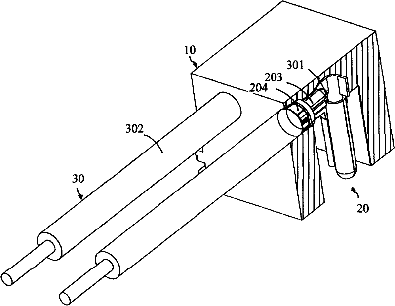
[0048] first as Figure 5 , on the thin metal strip (201), stamping and forming a plurality of hardware terminals (20) to form a product strip, so that each of the hardware terminals (20) has a hollow conductive pin part (202), a Conductive ring (203), a bundle of wire rings (204), and a joint (205), and the joints (205) of each hardware terminal (20) are still connected to the metal strip (201); prepare two Connecting wires, the conductive core material (301) of each connecting wire (30) is coated with an insulating coating material (302), and at least one end of the connecting wire (30) has no insulating coating and exposes the conductive core material (301);

[0049] Use riveting equipment such as a terminal crimping machine to crimp the bare conductive core material (301) at one end of the connecting wire (30) to the conductive ring (202) of the hardware terminal (20), and crimp the wire harness of the hardware terminal (20) ring (203) to bind the insulating coating materia...

specific Embodiment example 2

[0052] first as Figure 14 , on the thin metal strip (201), stamping and forming a plurality of hardware terminals (20) to form a product strip, so that each of the hardware terminals (20) has a hollow conductive pin part (202), a Conductive ring (203), a bundle of wire rings (204), two positioning elastic pieces (206) and a junction (205), and the junction (205) of each hardware terminal (20) is still connected with the metal strip (201 ) connected; prepare two connecting wires, make the conductive core material (301) of each connecting wire (30) coated with insulating coating material (302), and wherein at least one end has no insulating coating and exposes the conductive core material (301);

[0053] Use riveting equipment such as a terminal crimping machine to crimp the bare conductive core material (301) at one end of the connecting wire (30) to the conductive ring (202) of the hardware terminal (20), and crimp the wire harness of the hardware terminal (20) ring (203) to...


PUM


Abstract

The invention provides a manufacturing method and a manufacturing product of a power connector with wires. The method mainly comprises the following steps: first carrying out stamp molding on a plurality of hardware terminals by means of stamping on a thin metal material belt, and connecting the stamp molded hardware terminals with one another through combination parts to form a product material belt, wherein each hardware terminal is provided with at least one fixing ring, thus facilitating use of equipment such as a terminal crimping machine and the like to rivet connecting wires and continuously operating and being in favor of realizing automation; and then directly assembling the riveted hardware terminals and the connecting wires into an insulator or manufacturing the power connector with wires by means of embedding injection molding. By adopting the manufacturing method provided by the invention, while the production process and flow of the connectors are simplified, the reliability and production efficiency of the product are also improved, and the manufacturing cost is reduced at the same time.

Description

technical field [0001] The present invention provides a method for manufacturing a power connector with a wire and its products, especially refers to a plurality of hardware terminals formed by stamping to form a product array strip, which can then be quickly connected to the connecting wire by a terminal crimping machine or other crimping equipment , and directly assembled into an insulator for fixing or embedded in a mold and injected into a manufacturing method for a connector with a wire, and a power connector with a wire manufactured by this method. Background technique [0002] One of the known power connectors with wires, see Figure 18 [0003] The connector includes an insulator (71), more than two (including two) conductive pins (72), more than two (including two) conductive terminals (73) and more than two (including two) Connecting wire (74). [0004] The production method is as follows: [0005] Injection molding: filling an insulator in a mold to form an ins...

Claims


Application Information

Patent Timeline
IPC IPC(8): H01R13/02H01R43/00H01R43/16H01R43/18H01R43/20
Inventor 肖智勇
Owner SHENZHEN ZHITAI ELECTRONICS
Learn More