Boiler tube bank suspension device

A suspension device and boiler tube technology, applied to steam boilers, steam boiler accessories, steam boiler components, etc., can solve problems such as increased costs, difficulties, and large stress, and achieve cost savings for enterprises, easy suspension, and support Effect of reduced space requirements

Active Publication Date: 2013-08-21
SHANGHAI BOILER WORKS
View PDF4 Cites 0 Cited by
  • Summary
  • Abstract
  • Description
  • Claims
  • Application Information

AI Technical Summary

Problems solved by technology

This type of suspension structure for the pipe row 1' firstly has certain requirements for the space at both ends, which brings certain difficulties to the arrangement of other parts such as the pipe row 1'. Secondly, when the pipe row 1' is vertically When the displacement is large, it is necessary to install springs on the upper parts of the suspenders 7' at both ends, which increases the cost; and there are also certain requirements for the structure between the suspension point and the steel frame, because the suspenders 7' are easy to interact with other parts. Interference; when the tube row 1' has distortion and thermal deformation in its plane, a large stress will be generated at the welding connection between the steel plate 2' and the end plate 3'

Method used


Image

  • Boiler tube bank suspension device
  • Boiler tube bank suspension device
  • Boiler tube bank suspension device

Examples


Embodiment Construction

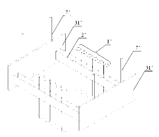
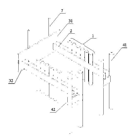
[0032] The following combination Figure 2~Figure 6 The invention is further elaborated, and a preferred embodiment of the invention is described in detail.

[0033] Such as figure 2 As shown, a boiler tube row suspension device includes a tube row 1, a pair of clamping steel plates 2, an end plate suspension device 3, a suspension tube support 4 and a boom 7, and the end plate suspension device 3 includes end The plate 31 and the end plate support 32 vertically arranged on the end plate 31; the suspension tube suspension device 4 includes a suspension tube 41 and a suspension tube support 42 arranged between the suspension tubes 41; the clamping steel plate 2 One end is set on the end plate suspension device 3, the other end is set on the suspension tube suspension device 4, and both ends of the clamping steel plate 2 can also be set on the suspension tube suspension device 4, in this embodiment One end of the clamping steel plate 2 is set on the end plate suspension devic...


PUM


Abstract

A boiler tube bundle suspension device, comprising a tube bundle (1), a pair of clamping steel plates (2), a end plate suspension device (3) and a suspension tube suspension device (4); the tube bundle (1) is connected with the clamping steel plate (2) via a pre-embedded part, the end plate suspension device (3) comprises an end plate (31) and an end plate support part (32) disposed on the end plate (31), and the suspension tube suspension device (4) comprises a suspension tube (41) and a suspension tube support part (42) disposed between the suspension tubes (41); one end of the clamping steel plate (2) is disposed on the end plate suspension device (3) and the other end is disposed on the suspension tube suspension device (4), or the two ends are both disposed on the suspension tube suspension device (4); the end plate support part (32) comprises a holding plate (321) and a support plate (322), the holding plate (321) is disposed on the end plate (31), the clamping steel plate (2) is connected with the support plate (322) and disposed on the clamping plate (321) via the support plate (322). The device can suspend the tube bundle (1) simply and conveniently, and provide a very good condition for the expansion under load of the tube bundle (1), avoiding interference with other parts and, at the same time, saving cost by eliminating spring hangers.

Description

technical field [0001] The invention relates to a suspension device, in particular to a boiler tube row suspension device. Background technique [0002] Such as figure 1 As shown, it is a schematic structural diagram of a boiler tube row suspension device in the prior art. The device includes a tube row 1', a clamping steel plate 2', an end plate 31' and a boom 7', and both ends of the clamping steel plate 2' are The frame structure of the end plate 31' is used for suspension. The load of the pipe row 1' is transmitted to the end plates 31' at both ends through the clamping steel plate 2'. The clamping steel plate 2' and the end plate 31' are directly welded. type, and then use the suspender 7' to transfer the load on the end plate 31' to the supporting structure such as the steel frame, so as to achieve the effect of suspending the pipe row 1'. This type of suspension structure for the pipe row 1' firstly has certain requirements for the space at both ends, which brings c...

Claims


Application Information

Patent Timeline
Patent Type & Authority Patents(China)
IPC IPC(8): F22B37/20F24H9/00
CPCF22B37/205F24H9/146F28F9/0131
Inventor 赵沈慧赵朋山周曙光叶伟民
Owner SHANGHAI BOILER WORKS
Why Eureka
Try Eureka