
Infrared night vision lens

An infrared and night vision technology, applied in the field of optical lenses, can solve problems affecting the appearance of cars, and achieve the effects of reducing the difficulty of implementation, saving installation space, and small volume

Active Publication Date: 2012-03-14
高海洋
View PDF3 Cites 4 Cited by
  • Summary
  • Abstract
  • Description
  • Claims
  • Application Information

AI Technical Summary

Problems solved by technology

Installing this kind of lens on the rear of the car will seriously affect the appearance of the car

Method used


Image

  • Infrared night vision lens
  • Infrared night vision lens
  • Infrared night vision lens

Examples


Embodiment Construction

[0015] The present invention will be further described below with reference to the accompanying drawings and in combination with preferred embodiments.

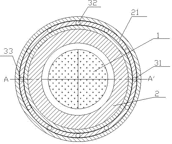
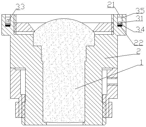
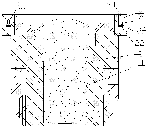
[0016] like figure 1 , 2 As shown, the infrared night vision lens of this embodiment is mainly composed of an optical lens 1, a front cover 2 and a lighting device;

[0017] The front end cover 2 is hollow and ring-shaped, and the hollow part is used to accommodate the lens 1; the edge of the front end cover 2 is provided with a PCB board fixing groove 21 for fixing the ring-shaped PCB board 34 of the lighting device, and the fixing groove 21 of this embodiment is for surrounding The lens 1 is provided with an annular groove 21 that is concentric with the hollow part. The bottom of the annular groove 21 is provided with an elastic plastic layer 22. Through the setting of the depth of the groove 21 and the thickness of the elastic plastic layer 22, the irradiation of the LED chip can be adjusted as required. angle.

[0018]...


PUM


Abstract

The invention discloses an infrared night vision lens which comprises an optical lens and a front end cover thereof, and also comprises an infrared LED chip and a PCB (Printed Circuit Board), wherein the front end cover is provided with a PCB fixing groove, the PCB is fixed in the PCB fixing groove, and the infrared LED chip is arranged on the PCB by adopting an SMT (Surface Mounting Technology). Compared with the prior art, the invention realizes integration of a night vision lighting device and the lens, and has the advantage of small volume.

Description

technical field [0001] The invention relates to an optical lens, in particular to a night vision lens. Background technique [0002] In the process of reversing into place, the driver cannot clearly see the rear end of the car through the car rearview mirror. Therefore, the rear of the car is likely to collide with objects at the rear end of the parking space during reversing, especially in unfamiliar places. In a parking environment or in a parking environment with insufficient light. Installing a camera device with night vision function at the rear of the car can solve the above problems, but most of the existing night vision cameras are used in the security field. The lens and infrared light tube adopt a split mode, and the infrared light tube is fixed on the around the lens. Therefore, the overall volume of the camera is relatively large. Installing this kind of lens on the rear of the car will seriously affect the appearance of the car. Contents of the invention ...

Claims


Application Information

Patent Timeline
IPC IPC(8): G02B13/14G02B13/00
Inventor 高海洋
Owner 高海洋
Learn More