
Dry-type permanent magnetic roller for separation of fine-disseminated ore

A mineral sorting and magnetic roller technology, which is applied in the fields of magnetic separation, solid separation, chemical instruments and methods, etc., can solve problems such as affecting product quality and recovery rate, problems with magnet fixing methods, and ineffective use of magnetic fields.

Inactive Publication Date: 2012-02-22
ANHUI UNIV OF SCI & TECH
View PDF6 Cites 13 Cited by
  • Summary
  • Abstract
  • Description
  • Claims
  • Application Information

AI Technical Summary

Problems solved by technology

At present, widely used large ore dry permanent magnet magnetic separators and magnetic pulleys, such as the CTDG series developed by the Ma'anshan Mining Research Institute and the CT series developed by the Beijing General Research Institute of Mining and Metallurgy, can be discarded in advance by 10% to 30%. % of the tailings, although to a certain extent, the grade of iron ore before entering the mill has been improved, the amount of milling has been reduced, and energy consumption has been reduced. However, this magnetic pulley dry separator is only suitable for the separation of ore materials with a particle size above 6mm. It is no longer suitable for low-grade ore and fine-grained minerals. Although wet separation can handle fine-grained minerals, it is greatly restricted in extremely cold and water-deficient areas.
In addition, the magnetic system of the current general-purpose magnetic separator not only has a small number of magnetic poles, but also has a very uneven magnetic force on the movement of the ore particles, which makes the two indicators of ore dressing—recovery rate and grade contradictory. The rate requires to increase the magnetic force, but the number of non-magnetic entrainment also increases, thereby reducing the grade; on the contrary, in order to improve the grade, it is required to reduce the magnetic force, but some magnetic substances will also be lost, which reduces the recovery rate.
Chinese patents CN2220900Y and CN2915265Y all relate to drum-type magnetic separators, but the above-mentioned magnetic separators mainly have the following problems during use: the magnetic poles of the magnetic field are traditionally changed alternately along the circumferential direction of the cylinder; there is a problem with the fixing method of the magnets, Causes the magnetic field to not be effectively utilized
In order to increase the magnetic energy level and gradient of the magnetic roller and enhance its ability to separate weakly magnetic minerals, the traditional magnetic roller adopts circular magnetic sheets or fan-shaped ones that are coaxial with the mandrel and arranged side by side along the mandrel axis. The magnetic pieces are combined, the magnetic poles corresponding to the adjacent circular magnetic pieces or fan-shaped magnetic pieces have the same polarity, and the circular magnetic pieces or fan-shaped magnetic pieces are sandwiched between high-permeability excitation materials, thus aggregated into axially arranged magnetic concentrators. Magnetic roller, although the magnetic field intensity of the magnetic collecting roller with this structure is increased to a certain extent, the depth of the magnetic field will be affected, and the magnetic field line changes periodically along the axis on the working surface, and is approximately equivalent in the circumferential direction. The magnetic field of each magnetic sheet is the highest at the side section, while the middle magnetic field is the weakest. During the sorting process, the magnetic field periodically changes in the direction of the axis, resulting in more ore being adsorbed at the strong magnetic position, and almost no material is adsorbed at the weak magnetic position, resulting in Materials cannot be evenly dispersed, resulting in the inclusion of non-magnetic materials, affecting product grade and recovery rate

Method used


Image

  • Dry-type permanent magnetic roller for separation of fine-disseminated ore
  • Dry-type permanent magnetic roller for separation of fine-disseminated ore
  • Dry-type permanent magnetic roller for separation of fine-disseminated ore

Examples


Embodiment Construction

[0020] The present invention will be further described below in conjunction with embodiment (accompanying drawing):

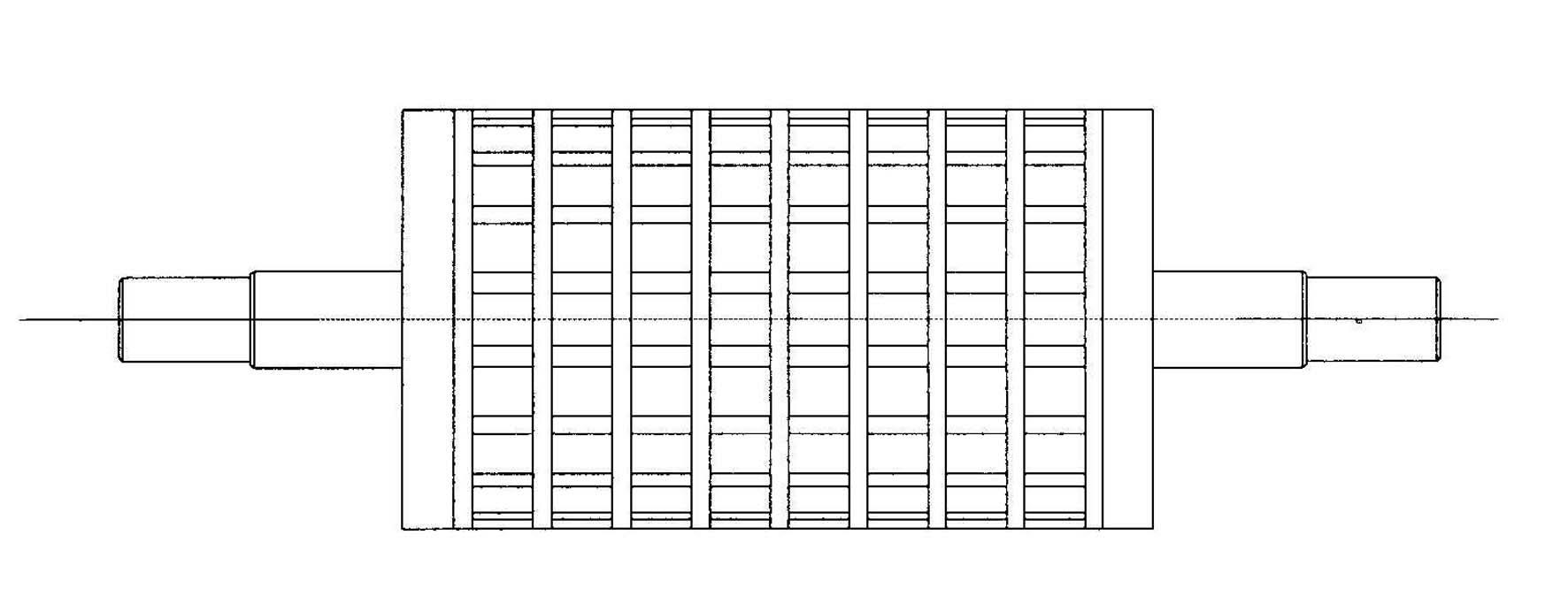
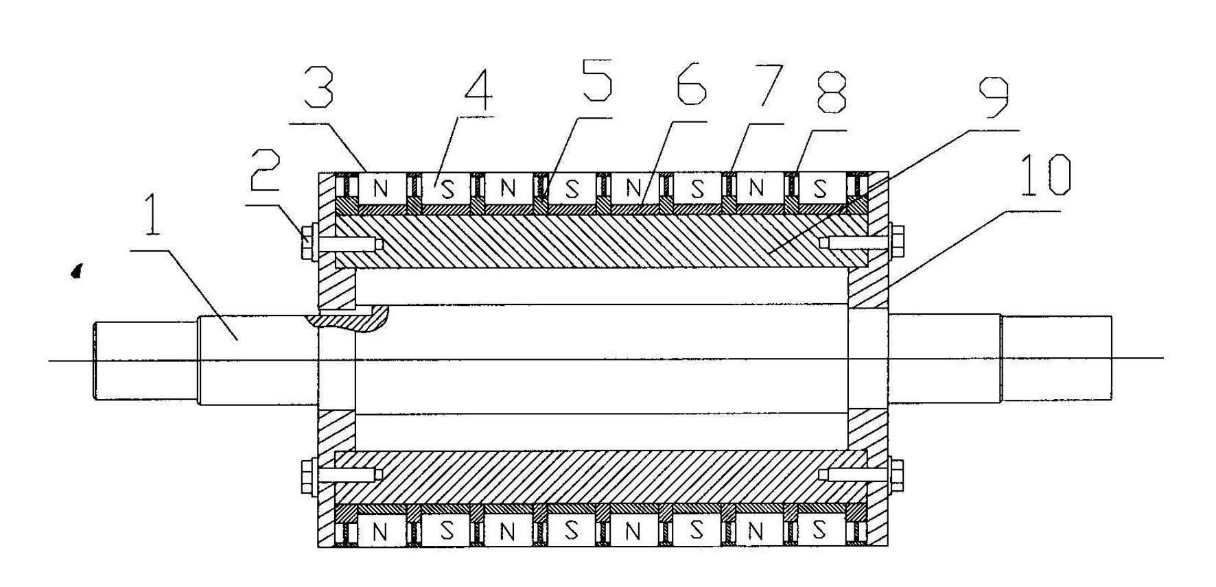
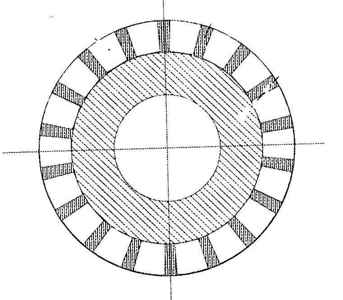
[0021] Such as figure 1 , 2 As shown, the dry-type permanent magnetic roller for the separation of fine-grained embedded minerals of the present invention is characterized in that: the magnetic roller includes a mandrel 1, which is sleeved on the mandrel in a manner coaxial with the mandrel 1 1, the non-magnetic cylinder 9 on the non-magnetic cylinder 9 is successively set with stainless steel rings 5 ​​and low-carbon steel rings 6; the outer ring surface of each low-carbon steel ring 6 is equipped with Several fan-shaped magnets 4 arranged at intervals, in the axial direction, between two adjacent fan-shaped magnets 4 are separated by a magnetic steel spacer ring 7 and a magnetic steel spacer ring rib 8, and the magnetic steel spacer ring 7 and the magnetic steel spacer rib 8 are non-magnetic materials, and welded together (see Figure 5 , 6 , 7, 8), this ...


PUM


Abstract

A dry-type permanent magnetic roller for separation of fine-disseminated ore is characterized in that: the magnetic roller comprises a magnetic roller core shaft, a non-magnetic conductive cylinder by which the magnetic roller core shaft is sleeved in a manner that the cylinder has a same shaft center as the magnetic roller core shaft, stainless steel rings and low-carbon steel rings by which the non-magnetic conductive cylinder are orderly sleeved with intervals; a magnet ring formed by a plurality of spaced sector magnets and magnetism isolating materials are mounted surrounding an outer ring surface of each low-carbon steel ring, and a non-magnetic conductive material ring is mounted surrounding an outer ring surface of each stainless steel ring; a stainless steel wrapping layer is disposed on the outermost layer of the magnetic roller; the sector magnets are arranged with the N and S poles being alternative in the axial and circumference directions of the whole roller, and the magnetic poles are in pairs with each magnetic pole being an opposite magnetic pole to its adjacent magnetic pole.

Description

technical field [0001] The invention relates to magnetic mineral separation equipment in the field of mineral processing engineering, especially suitable for magnetic separation of fine-grained iron ore materials, and specifically relates to a dry permanent magnet for fine-grained mineral separation magnetic roller. The magnetic roller of the present invention can also be used to remove magnetic impurities and purify magnetic materials from non-magnetic materials, and can also be used in metallurgy, chemical industry, cement, grain and other departments and slag treatment. technical background [0002] Magnetic separation is an important method in material separation and treatment technology, and its process is clean and pollution-free. Permanent magnet magnetic separation equipment is widely used in the field of mineral processing because of its low energy consumption, low cost, simple structure, convenient operation, no pollution or less pollution. In recent years, the p...

Claims


Application Information

Patent Timeline
IPC IPC(8): B03C1/02
Inventor 焦红光刘松田中良朱金波吴金保张明旭闵凡飞王超
Owner ANHUI UNIV OF SCI & TECH
Learn More