Charging system for electric vehicles

An electric vehicle and charging system technology, applied in electric vehicles, battery circuit devices, current collectors, etc., can solve the problems of high grid dependence and inability to charge electric vehicles, and achieve the effect of reducing thermal power consumption and standardizing charging behavior.

Inactive Publication Date: 2012-02-15
CHERY AUTOMOBILE CO LTD
View PDF5 Cites 4 Cited by
  • Summary
  • Abstract
  • Description
  • Claims
  • Application Information

AI Technical Summary

Problems solved by technology

[0006] The technical problem to be solved by the present invention is that the existing electric vehicle charging equipment is highly dependent on the power grid, and the electric vehicle cannot be charged due to frequent power outages in areas where electric power is scarce

Method used


Image

  • Charging system for electric vehicles
  • Charging system for electric vehicles
  • Charging system for electric vehicles

Examples


Embodiment 1

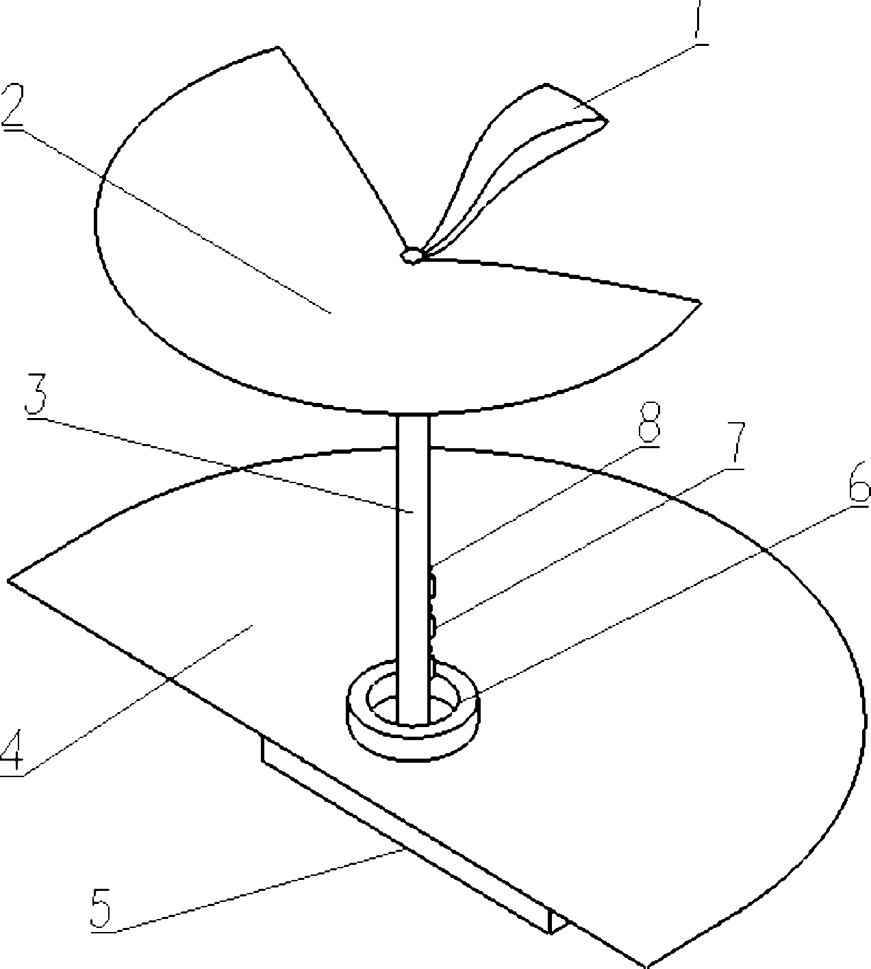
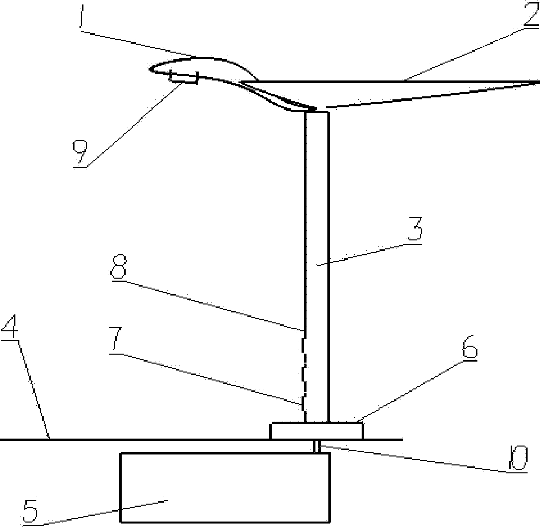
[0037] Such as Figure 1-3 Shown is the structure diagram of the electric vehicle charging system of the present invention.

[0038] The electric vehicle charging system mainly includes the following parts: energy storage device, electric energy charging device and solar power supply device.

[0039] energy storage device

[0040] The energy storage device is connected with the grid system through a cable, and is used for receiving and storing electric energy of the grid system.

[0041] Electric energy charging device

[0042] It is electrically connected with the energy storage device, and is used to transfer the electric energy in the energy storage device to the electric vehicle that needs power supply.

[0043] The electric energy charging device includes a charging socket arranged on the cylinder and a card-swipe billing induction system. The charging socket is electrically connected to the energy storage device through a cable, and the card-swipe billing induction sy...

Embodiment 2

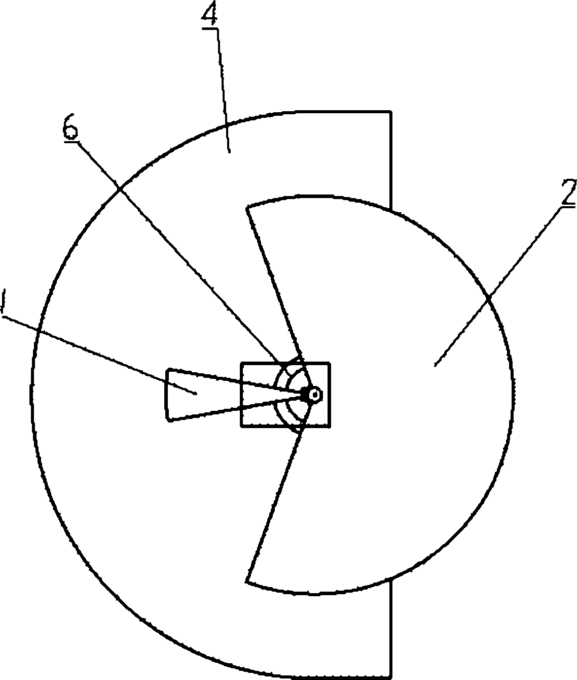
[0054] Such as Figure 4-6 Shown is another embodiment of the electric vehicle charging system of the present invention, the structure of the electric vehicle charging system is basically the same as that of embodiment 1, the difference lies in the structure and shape of the solar battery panel, the solar battery panel of this embodiment It is a circular plane as a whole, and a rainwater diversion groove 10 is left on the upper surface of the solar cell panel, so as to discharge rainwater in time in rainy days and avoid damage to the solar cell panel.

Embodiment 3

[0056] Such as Figure 7-9 Shown is another embodiment of the electric vehicle charging system of the present invention, the structure of the electric vehicle charging system is basically the same as that of embodiment 1, the difference lies in the structure and shape of the solar battery panel, the solar battery panel of this embodiment It includes several fan blade-shaped solar panels arranged radially.

[0057] The structural forms of the solar cell panels in the above-mentioned embodiments are not limited to the above-mentioned types, and different shapes can be selected according to different local areas on the side of the road or in the community, which will not be repeated here.


PUM


Abstract

The invention discloses a charging system for electric vehicles. The charging system comprises an energy storage device and an electrical energy charging device, wherein the energy storage device is connected with a power grid system by a cable, and used for transmitting the electrical energy of the power grid system to the energy storage device for storing the electrical energy charging device is electrically connected with the energy storage device, and used for transmitting the electrical energy in the energy storage device to an electric vehicle required to be changed; the charging system also comprises a solar energy supply device; and the solar energy supply device is arranged on the ground and connected with the energy storage device by a cable, and used for receiving solar energy and converting the solar energy into electrical energy, and storing converted electrical energy into the energy storage device by a cable, wherein the electrical energy is used for supplying power for electric vehicles. The charging system for electric vehicles disclosed by the invention fully uses renewable solar energy resources, can be used as a street lamp in night and also can be used in an electric-vehicle parking lot in the evening for charging electric vehicles; moreover, the charging system for electric vehicles also can be used as a resting place for people in the day.

Description

technical field [0001] The invention relates to the field of electric vehicle charging equipment, and specifically designs an electric vehicle charging system. Background technique [0002] Electric vehicles can achieve zero exhaust emissions, which is very beneficial to environmental protection and air cleanliness, and is the direction of future development. Currently, there are special charging stations for electric vehicles, which adopt a business model similar to traditional gas stations; in addition, in China Patent document CN201020277227.8 discloses an electric vehicle charging pile device, including a top cover, a pile body, upper and lower supports, a base, a base sheath, etc., the base and the base shield are sequentially fixed on the bottom of the pile body, and a The charging circuit and the upper bracket and the lower bracket, the top cover and the upper bracket are provided with a bolt connection fixing structure, the top cover is fixed on the top of the pile b...

Claims


Application Information

Patent Timeline
Patent Type & Authority Applications(China)
IPC IPC(8): H02J7/00
Inventor 赵君
Owner CHERY AUTOMOBILE CO LTD
Why Eureka
Try Eureka