
Optical fiber end surface processing method

An optical fiber end face treatment and optical fiber end face technology, which is applied to the coupling of optical waveguides and other directions, can solve the problems of complex production process of the optical fiber grinding treatment method, poor optical fiber loss and reflection loss indicators, high manufacturing cost and difficulty, and avoid adverse effects. , Guaranteed physical contact, low cost effect

Inactive Publication Date: 2012-02-08
JIANGSU UNIKIT OPTICAL TECH
View PDF4 Cites 11 Cited by
  • Summary
  • Abstract
  • Description
  • Claims
  • Application Information

AI Technical Summary

Problems solved by technology

[0003] Although the optical fiber cutting method is simple, although the cutting end face is flat, it is limited by the accuracy of the optical fiber cleaver, and there will be defects on the cutting end face, and the angle of the cutting end face is randomly distributed , leading to poor loss and reflection loss indicators during fiber splicing
[0004] The optical fiber end face processed by the optical fiber polishing method, especially the spherical optical fiber end face, can realize the optical fiber core without coating and adding refractive index matching liquid. The physical contact between them, the splicing performance is good, and the stability is high. However, whether the optical fiber polishing method is made in a factory or on-site, the production process is relatively complicated, and the manufacturing cost and difficulty are high.

Method used


Image

  • Optical fiber end surface processing method
  • Optical fiber end surface processing method
  • Optical fiber end surface processing method

Examples


Embodiment Construction

[0016] In conjunction with the accompanying drawings, the present invention is described in detail.

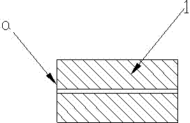
[0017] Such as figure 1 As shown, to prepare the fiber end face, the fiber end 1 is cleaved into a smooth fiber end face a by the fiber cleaver, and the fiber end face a has a certain inclination angle affected by the precision of the cleaver.

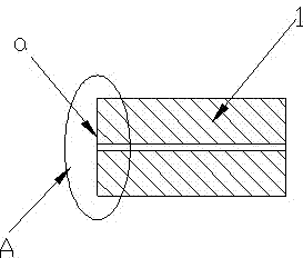
[0018] Such as figure 2 As shown, the cut optical fiber end 1 is positioned in the heat source A, and the heat source A and the intensity of the heat source A can be properly adjusted according to the different optical fiber materials and the application of the optical fiber.

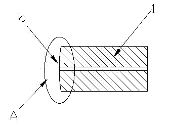
[0019] Such as image 3 Shown: using electric arc, laser or flame and other thermal melting treatment methods, the completely cut optical fiber end 1 is finitely melted, and the limitedly fused optical fiber end 1 is formed into a smooth spherical or quasi-spherical surface b by the surface tension of the liquid, and after cooling and solidification Complet...


PUM


Abstract

The invention discloses an optical fiber end surface processing method, which comprises the following steps of: enabling the temperature of the end part (1) of the optical fiber to instantly reach or exceed the smelting point of an optical fiber material by providing a heat source (A); and enabling the end surface (a) of the optical fiber to form a smooth spherical surface or a quasi-spherical surface by utilizing the surface tension at the end part of the liquid optical fiber, so as to realize physical contact of end surfaces of fibre cores when the optical fibers are connected to achieve a grinding method processing effect. Compared with the prior art, the optical fiber end surface hot-melting method provided by the invention has the advantages of avoiding the adverse influence caused by reflective index matching liquid and the like, ensuring the physical contact of the fiber cores when the optical fibers are connected and also ensuring that the connection performance meets requirements. Meanwhile, equipment needed by the method disclosed by the invention is lightweight and portable, simple to operation and convenient to observe; and the optical fiber end surface processing method can realize repeated processing on the end surface of the optical fiber under the condition of not damaging any other assemblies and achieve the purpose of low cost.

Description

technical field [0001] The present invention relates to a treatment method for the shape of the end face of the optical fiber. Heat sources such as arcs, lasers, and flames are used to heat-melt the end of the optical fiber, and the surface tension of the end of the liquid optical fiber is used to form a smooth spherical or quasi-spherical surface on the end of the optical fiber. Moreover, the transmission characteristics of the original optical fiber waveguide are retained, and the physical contact of the fiber core end face is realized when the optical fiber is spliced, achieving the effect of grinding method treatment. Background technique [0002] At present, the fiber end face treatment methods for the non-permanent fixed connection between the fiber and the fiber and the fiber and the device mainly include two methods: fiber cutting and fiber grinding. The end face, optical fiber polishing treatment method is to use the multi-process grinding of the optical fiber grind...

Claims


Application Information

Patent Timeline
Patent Type & Authority Applications(China)
IPC IPC(8): G02B6/255
Inventor 吕根良赵毅徐宁钱晨马正北
Owner JIANGSU UNIKIT OPTICAL TECH
Learn More