
Heat dissipation device for cabinet and method for heat dissipation of cabinet

A heat dissipation device and cabinet technology, which is applied in cooling/ventilation/heating renovation, instrumentation, electrical digital data processing, etc., to achieve the effects of increasing the exchange heat flow rate, balancing cooling, and optimizing the structure of the air duct

Active Publication Date: 2012-02-01
中科腾龙信息技术有限公司
View PDF5 Cites 16 Cited by
  • Summary
  • Abstract
  • Description
  • Claims
  • Application Information

AI Technical Summary

Problems solved by technology

[0003] At present, the heat dissipation that the standard 42U cabinet can carry is between 15 and 20KW, and the design heat dissipation of the cabinet with a closed cooling system can only reach 35KW

Method used


Image

  • Heat dissipation device for cabinet and method for heat dissipation of cabinet
  • Heat dissipation device for cabinet and method for heat dissipation of cabinet
  • Heat dissipation device for cabinet and method for heat dissipation of cabinet

Examples


Embodiment Construction

[0026] Considering the problems existing in the related art, the present invention provides a cooling device for a cabinet and a method for using the cooling device to dissipate heat. Embodiments of the invention are described in detail below, examples of which are illustrated in the accompanying drawings. It should be understood that the embodiments described below by referring to the figures are exemplary only for explaining the present invention, and should not be construed as limiting the present invention.

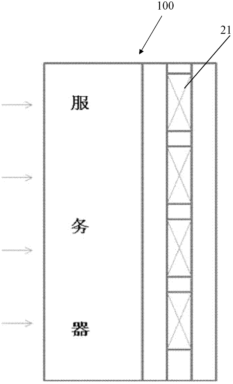
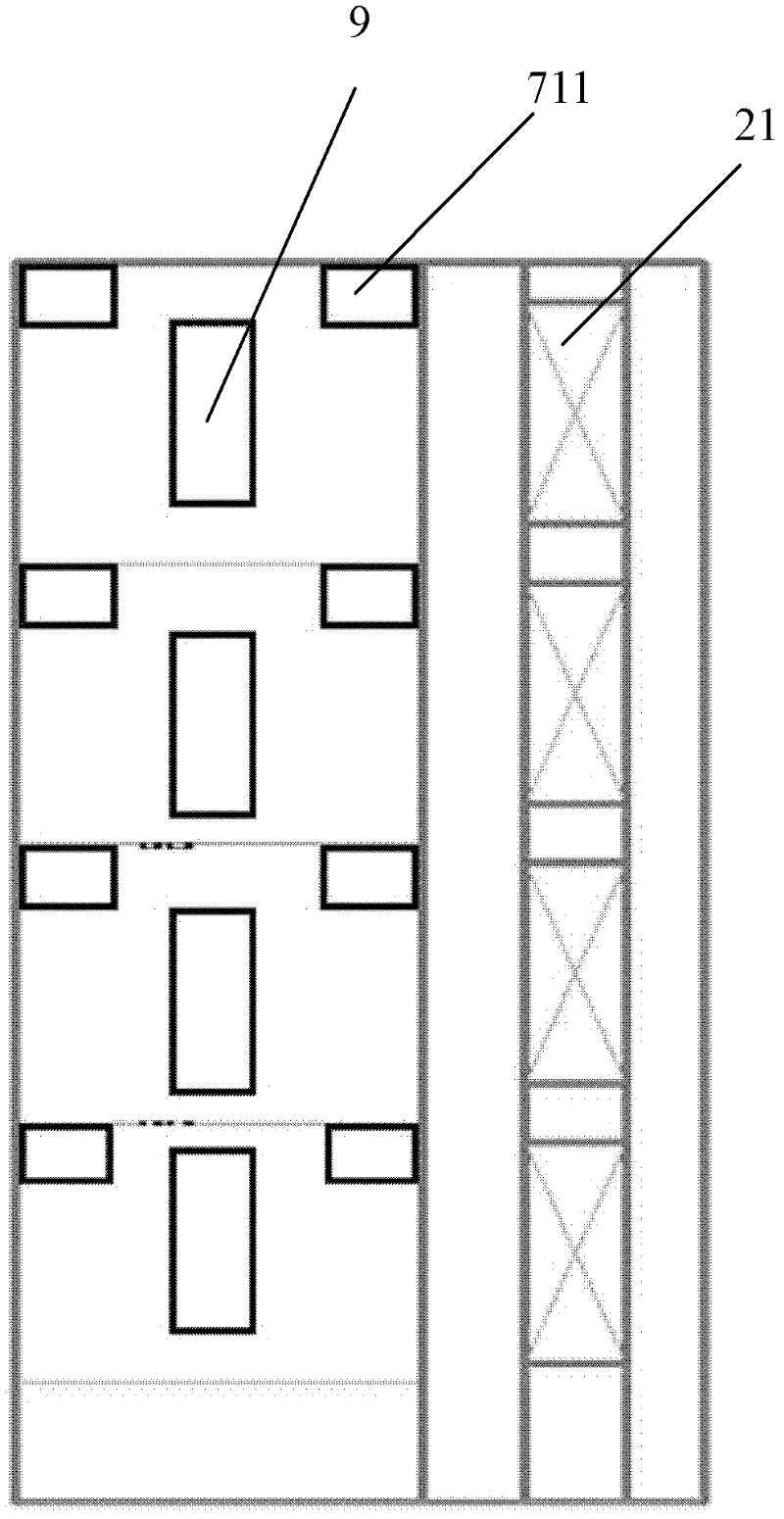
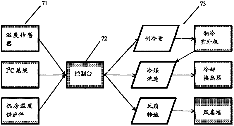
[0027] attached Figures 1 to 3 to a schematic diagram of an embodiment of a heat sink according to the present invention, wherein figure 1 is a schematic diagram of one embodiment of the heat sink, figure 2 is a schematic diagram of another embodiment of the heat sink, image 3 is a schematic diagram of the thermal management and health management system in a cooling device. According to the present invention, the illustrated heat dissipation device is used to d...


PUM


Abstract

The invention provides a heat dissipation device and a heat dissipation method for a cabinet. Heating parts are arranged in the cabinet. The heat dissipation device comprises a cooling fan wall and control system and a heat dissipation air duct, wherein the cooling fan wall and control system comprises a fan wall which is arranged at the back of the cabinet and is provided with groups of fans, and the heat dissipation air duct is arranged in the cabinet and is communicated with the fan wall. By adopting the heat dissipation device and the heat dissipation method provided by the invention, heat generated by a server in the cabinet can be dissipated in time, and the heat exchange efficiency and the exchanged heat flow rate of a clustered system are improved; by dividing the heat dissipation air duct into a plurality of areas which are isolated from each other, the structure of the air duct can be optimized and the balanced cooling of the cabinet is realized; and by arranging a heat management and health monitoring system, an optimal heat dissipation effect can be reached. Besides, the heat dissipation effect of the server cabinet can be ensured to satisfy the requirements of high efficiency and high density. Moreover, the energy loss of all equipment in the cabinet can be reduced and the maintenance and use costs are reduced.

Description

technical field [0001] The invention relates to a cooling device for a cabinet and a method for cooling the cabinet. Background technique [0002] The proposal and development of the concept of cloud computing has led to the rapid development of server clusters. The design of server clusters has increasingly become the key direction of server design, and server design ideas around data centers emerge in endlessly. With the increasing intensification of data centers and the development of miniaturization and centralization of servers, the power consumption density per unit space is getting higher and higher. In order to ensure the normal operation of the server system, higher requirements are put forward for heat dissipation and mechanism design. [0003] At present, the heat dissipation that a standard 42U cabinet can carry is between 15 and 20KW, and the design heat dissipation of a cabinet with a closed cooling system can only reach 35KW. Due to the increase in the cost...

Claims


Application Information

Patent Timeline
Patent Type & Authority Applications(China)
IPC IPC(8): H05K7/20G06F1/20
Inventor 李程张旭史卓亚骆起昕朱越戴荣王璟
Owner 中科腾龙信息技术有限公司
Learn More