
Field emission triode structure based on graphene

A graphene and field emission technology, applied in the direction of control electrodes, parts of discharge tubes/lamps, electrical components, etc., can solve the problems of reducing the utilization rate of electrons, difficult processing and preparation, etc., to avoid electron beam focusing and emission current. Mutual influence, the effect of improving the total field emission current and good electrical conductivity

Inactive Publication Date: 2012-02-01
SOUTHEAST UNIV
View PDF4 Cites 28 Cited by
  • Summary
  • Abstract
  • Description
  • Claims
  • Application Information

AI Technical Summary

Problems solved by technology

In order to ensure sufficient emission current and improve the uniformity of emission current, it is necessary to reduce the membrane pore size as much as possible, usually the membrane pore size is only 10-20 microns, which brings great difficulties to the processing and preparation
[0005] Due to the electron lens effect of the gate film hole electrode, the electrons emitted from the emitter are easily intercepted by the gate electrode, thereby reducing the utilization rate of electrons

Method used


Image

  • Field emission triode structure based on graphene
  • Field emission triode structure based on graphene
  • Field emission triode structure based on graphene

Examples


Embodiment Construction

[0018] The present invention will be described below with reference to the accompanying drawings.

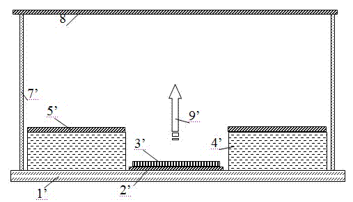
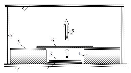
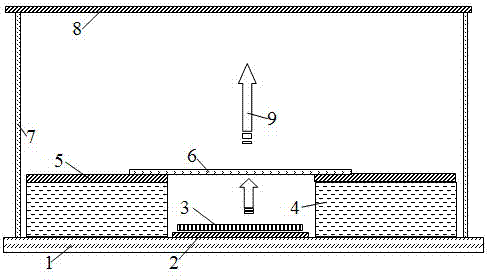
[0019] The present invention proposes a graphene-based field emission triode structure, the field emission triode structure includes a cathode substrate, a cathode electrode, a field emitter for emitting electron beams, an insulating dielectric layer, a grid electrode, and a graphene layer , support body and anode; Wherein:

[0020] A cathode electrode is arranged on the cathode substrate, a field emitter is arranged on the cathode electrode, an insulating medium layer is located on the cathode substrate, a grid electrode is arranged on the insulating medium layer, and a graphene layer is arranged on the grid electrode. The anode is located above the cathode substrate and opposite to the cathode substrate, and is fixed to the cathode substrate through a support. The electron beam emitted by the field emitter is modulated by the grid electrode and bombards the anode through the ...


PUM

PropertyMeasurementUnit
Thicknessaaaaaaaaaa

Abstract

The invention relates to a field emission triode structure based on graphene. The field emission triode structure comprises a cathode substrate (1), a support body (7) and an anode (8), wherein the support body (7) is positioned on the cathode substrate (1), the anode (8) is positioned on the support body (7) and parallel to the cathode substrate (1), and the cathode substrate (1), the support body (7) and the anode (8) constitute a cavity; and the field emission triode structure also comprises a cathode electrode (2) positioned in the enclosed cavity, a field emission body (3) for emitting electron beams (9), an insulated dielectric layer (4), a grid electrode (5) and the graphene (6). The field emission triode structure based on the graphene, provided by the invention, can realize high-current uniform emission, has the capability of effectively separating emission of field emission current from acceleration and focusing of electronic beams and can be used for a cold cathode X-ray source, a microwave amplifier tube and a field emission display.

Description

technical field [0001] The invention relates to a field emission triode structure, which relates to device structure design and material preparation of field emission electronic devices. Background technique [0002] Field emission electronic devices use cold cathodes as electron emission sources, which have the characteristics of fast response, low power and high reliability. However, there is still a certain gap between field emission electronic devices and marketization, and there are some key technical bottlenecks. Among them, the design and preparation of the triode structure is an important factor affecting the practical application of field emission devices. [0003] Field emission electronic devices have two physical processes of electron field emission and electron focusing / acceleration, and excellent electron beam characteristics cannot be obtained only by using a dipole structure. Therefore, a triode structure is the core of a field emission electronic device. I...

Claims


Application Information

Patent Timeline
IPC IPC(8): H01J1/304H01J1/46
Inventor 雷威张晓兵李驰娄朝刚崔一平陈静
Owner SOUTHEAST UNIV
Learn More