Charge control system
A charge control, charge and discharge technology, applied in the direction of battery temperature control, control device, battery/fuel cell control device, etc., can solve the problems of large battery heat dissipation, battery temperature drop, etc., and achieve the effect of extending the cruising distance
- Summary
- Abstract
- Description
- Claims
- Application Information
AI Technical Summary
Problems solved by technology
Method used
Image


Examples
no. 1 approach
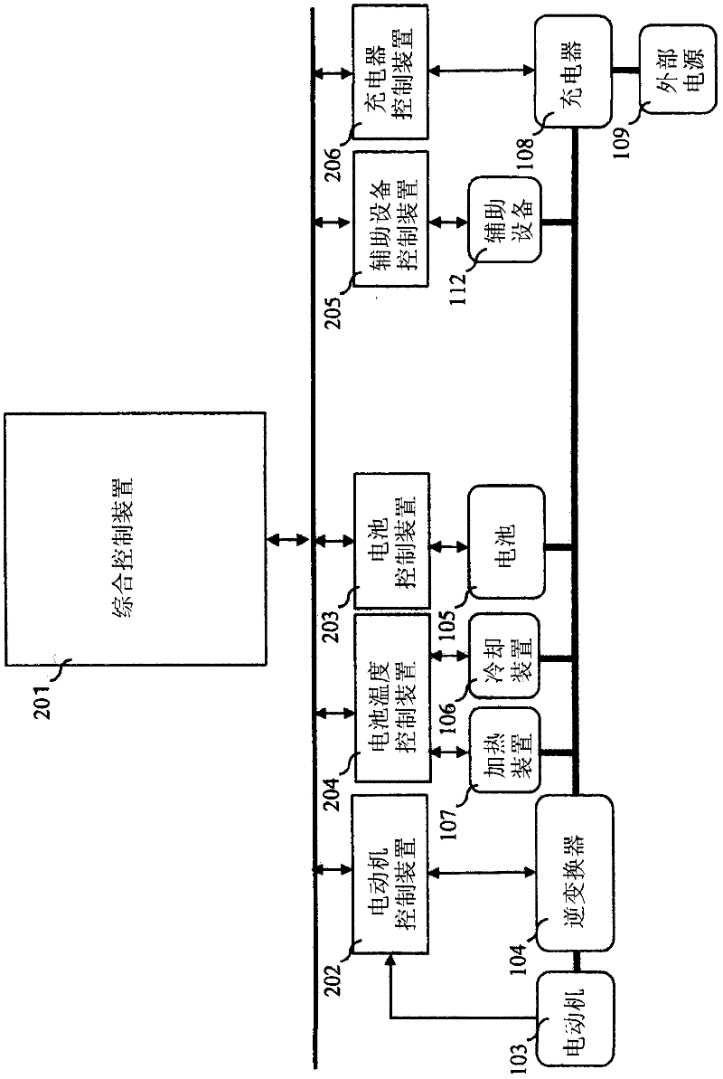
[0060] figure 2 It is a diagram showing the configuration of the charging control system according to the first embodiment of the present invention. This charging control system has: an integrated control device 201; a motor control device 202 for controlling the inverter 104 and the motor 103; a battery control device 203 for controlling the battery 105; a battery for controlling the cooling device 106 and the heating device 107 temperature control means 204 ; auxiliary equipment control means 205 for controlling the auxiliary equipment 112 ; and charger control means 206 for controlling the charger 108 . The control devices described above are connected to each other through a communication network provided in the electric vehicle 101 , for example, CAN (Controller Area Network, Controller Area Network).
[0061] exist figure 2 In the charging control system, the inverter 104, the cooling device 106, the heating device 107, the auxiliary equipment 112 and the charger 108...
no. 2 approach
[0103] Next, a charging control system according to a second embodiment of the present invention will be described. The difference between this embodiment and the above-mentioned first embodiment is that in Figure 4 In the second charging mode of step S402, the battery temperature T is controlled so that the battery temperature T becomes the target battery temperature T_target in consideration of the outside air temperature T_out, rather than the charge-discharge allowable battery temperature lower limit T_min. The target battery temperature T_target can be obtained by adding the offset temperature delta_T determined based on the outside air temperature T_out to T_min.
[0104] Figure 9 means that in the charging control system of the second embodiment of the present invention, instead of Figure 7 A flowchart of the processing performed in the second charging mode by the processing of the flowchart. in, Figure 9 in the flow chart with Figure 7 Likewise, for Figure ...
no. 3 approach
[0127] Next, a charging control system according to a third embodiment of the present invention will be described. The difference between this embodiment and the above-mentioned second embodiment is that in Figure 9 In step S902, the offset temperature delta_T is determined according to the predicted load of the battery 105 and the outside air temperature T_out, and the target battery temperature T_target is calculated.
[0128] Figure 13 It is a diagram showing the configuration of a charging control system according to a third embodiment of the present invention. The charging control system and figure 2 Compared with the above, the difference lies in that a vehicle peripheral information acquisition device 1301 and an information communication device 1302 are provided, and an LUT ( Look Up Table, Look Up Table) 1303.
[0129]Vehicle surrounding information acquiring device 1301 is a device that acquires information on road conditions around electric vehicle 101 as veh...
PUM
 Abstract
Description
Claims
Application Information
 - R&D
- Intellectual Property
- Life Sciences
- Materials
- Tech Scout
- Unparalleled Data Quality
- Higher Quality Content
- 60% Fewer Hallucinations
Browse by: Latest US Patents, China's latest patents, Technical Efficacy Thesaurus, Application Domain, Technology Topic, Popular Technical Reports.
© 2025 PatSnap. All rights reserved.Legal|Privacy policy|Modern Slavery Act Transparency Statement|Sitemap|About US| Contact US: help@patsnap.com