
Temperature adjustment system

A temperature control system and catalyst technology, applied in the field of temperature systems, can solve problems such as accelerating fuel consumption in fuel cells, and achieve the effects of suppressing power consumption, reducing charging frequency, and prolonging life.

Active Publication Date: 2013-10-09
MIHAMA CORP
View PDF10 Cites 1 Cited by
  • Summary
  • Abstract
  • Description
  • Claims
  • Application Information

AI Technical Summary

Problems solved by technology

It also accelerates the consumption of fuel in the fuel cell

Method used


Image

  • Temperature adjustment system
  • Temperature adjustment system
  • Temperature adjustment system

Examples


Embodiment 1)

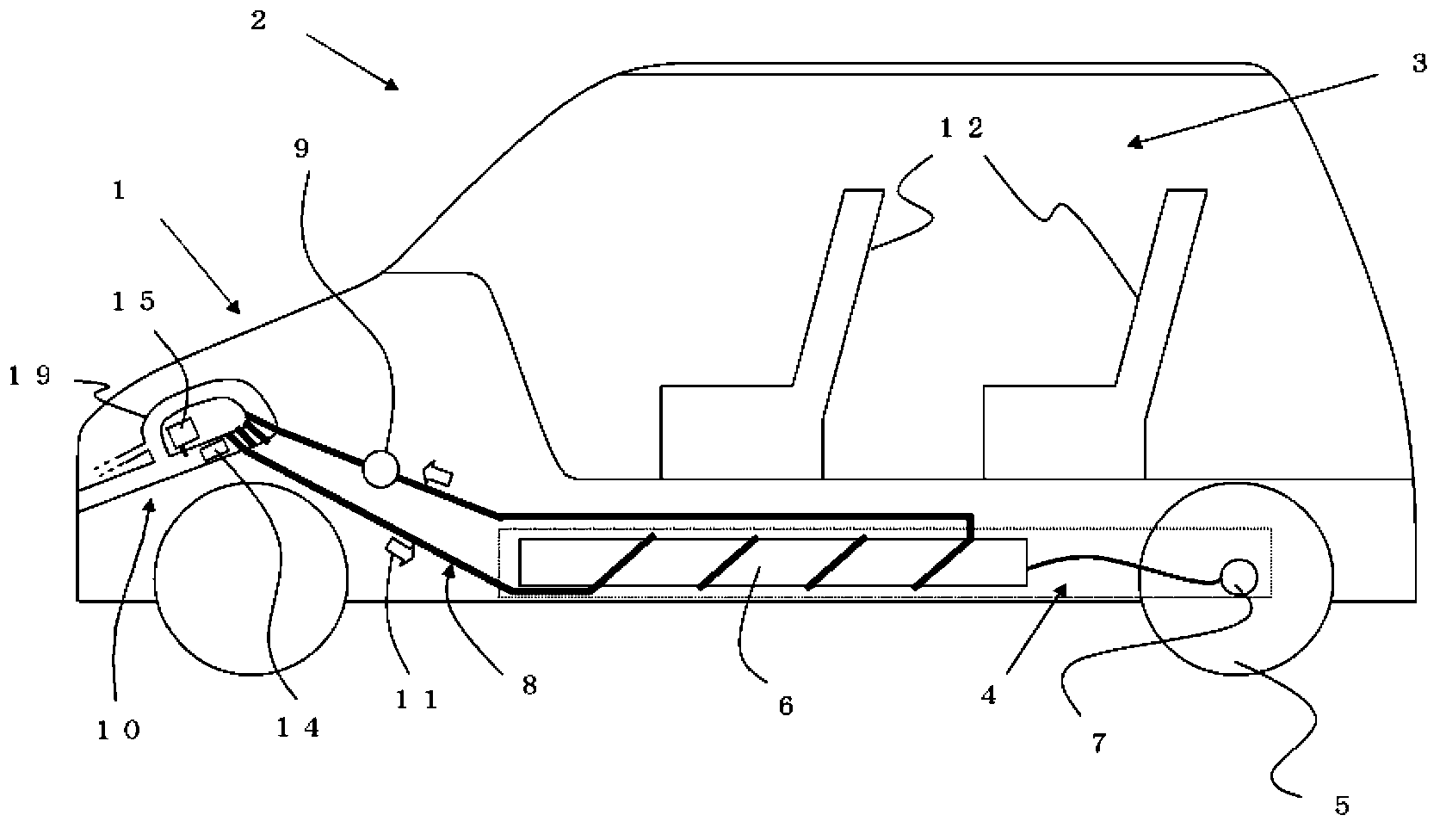
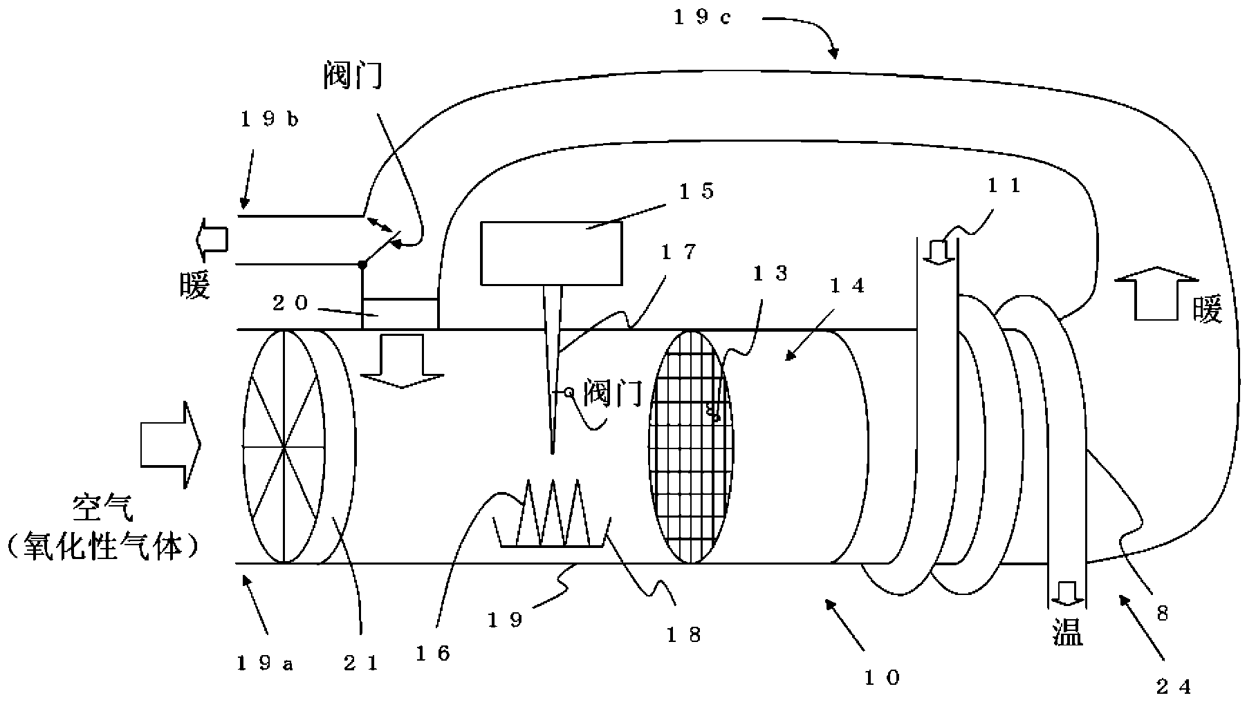
[0161] Carry out the following experiment: prepare to have such figure 2 The temperature control system 1 of the present invention of the catalyst heater 10 shown (in addition, as Figure 8 , In the seat 12 prepared separately, there is a liquid feeding pipe 8), and using this temperature control system of the present invention, in an environment where the outside air is 0 ℃, in the catalyst heater 10, the air and fuel are It reacts on the catalyst 13 and at the same time circulates a part of them and generates heat. The secondary battery 6 and the seat 12 are heated through the liquid feeding pipe 8 or the temperature control duct 27, and at the same time, the air conditioning duct 28 passes through the duct 28 for a specific time. Heat the same space as the carriage and maintain it at a fixed temperature (20℃) (such as Picture 10 system).

[0162] In addition, the secondary battery or the seat is heated so that the temperature is the same as the temperature when the outside ai...

Embodiment 2)

[0172] Except for the same equipment as in Example 1, a thermoelectric element 26 is further arranged.

[0173] In addition, thermoelectric elements 26 such as Picture 9 As shown, it is connected to a conduit 19 near the catalyst carrier 14 or downstream thereof. Only supply a small amount of fuel methanol, and try to generate electricity through the Seebeck effect caused by the temperature difference in the above-mentioned parts of the system.

[0174] After measuring the temperature near the catalyst carrier (as the temperature of the catalyst carrier) and the temperature in the downstream area (as the temperature of the reacted gas) at this time, the following results are obtained: Figure 13 Chart.

[0175] by Figure 13 It can be seen that the catalyst carrier itself rises to about 200°C. On the other hand, the gas temperature rose to about 430°C. In addition, using their temperature difference of 200°C or more, the thermoelectric element can effectively store electricity i...


PUM


Abstract

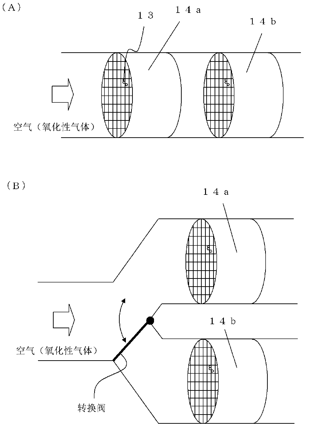
The present invention is a temperature adjustment system for adjusting the temperature of each portion of an automobile provided with: at least a motor compartment in which a secondary battery or a fuel cell for driving wheels by means of motors are mounted; and a cabin. The system has at least one or more catalyst heaters provided with catalysts and fuel tanks. The catalyst heater generates heat when oxidizing gas and fuel from the fuel tank are supplied to the catalyst. At least a portion of gas warmed by the heat generated by supplying the oxidizing gas and the fuel to the catalyst is circulated and supplied to the catalyst, and the temperature of each portion of the automobile is adjusted utilizing the heat generated by the catalyst heater. In an electric automobile, etc., the system prevents a decrease in the primary function of the automobile in cold regions and can efficiently adjust the temperature of each portion of the automobile to enable the automobile to travel comfortably.

Description

Technical field [0001] The present invention relates to a system for adjusting the temperature of various parts of a car, such as an electric car, a hybrid (gasoline engine + electric) car, or a fuel cell car, using a secondary battery or a fuel cell, etc., with an engine Drive the wheels. Background technique [0002] In recent years, one of the environmental issues is the increase in carbon dioxide. Carbon dioxide is cited as one of the main causes of global warming, and therefore efforts are made to suppress its production, for example, efforts are made to suppress the amount of exhaust gas emitted from automobiles and the like. [0003] Therefore, people are looking forward to the development of electric vehicles, hybrid vehicles, or fuel cell vehicles (hereinafter referred to as electric vehicles, etc.) that do not emit carbon dioxide or can suppress carbon dioxide generation compared to conventional products (refer to Patent Document 1) . [0004] These electric vehicles, et...

Claims


Application Information

Patent Timeline
Patent Type & Authority Applications(China)
IPC IPC(8): B60H1/22H01M8/00
CPCY02E60/12H01M10/5093B60H1/2206Y02E60/50B60H1/2209H01M10/5006H01M8/04014B60H1/2212H01M2220/20H01M2250/20H01M10/615H01M10/66Y02T90/40Y02E60/10H01M8/00B60H1/22
Inventor 美浜健山边贤一郎
Owner MIHAMA CORP
Learn More