Hydraulic jack

A hydraulic jack and high-pressure technology, applied in the direction of lifting devices, etc., can solve the problems of restricting the range of use of the jack, and the jack cannot be used upside down or flat, achieving the effect of strong adaptability and expanding the range of use

Inactive Publication Date: 2012-01-11
王欣
View PDF0 Cites 3 Cited by
  • Summary
  • Abstract
  • Description
  • Claims
  • Application Information

AI Technical Summary

Problems solved by technology

[0002] At present, the general hydraulic jack is composed of oil suction oil passage, oil pressure oil passage, oil discharge oil passage, base, piston cylinder, and manual plunger pump. The one-way ball valve is opened and the oil pressure check valve is closed. At this time, the oil is sucked into the pump from the oil storage tank. When the plunger is down, the oil suction check valve is closed and the oil pressure check valve is opened. The channel enters the high-pressure chamber and pushes the piston upward to achieve the purpose of lifting. This kind of hydraulic jack is widely used because of its delicate structure, convenient handling and simple maintenance. However, in some other occasions, it is necessary to turn the jack upside down or lay it flat. At this time, due to the structural reasons of the existing jack, the existing jack cannot be used upside down or laid flat, which not only causes trouble for some work, but also limits the scope of use of the jack.

Method used


Image

  • Hydraulic jack

Examples


Embodiment Construction

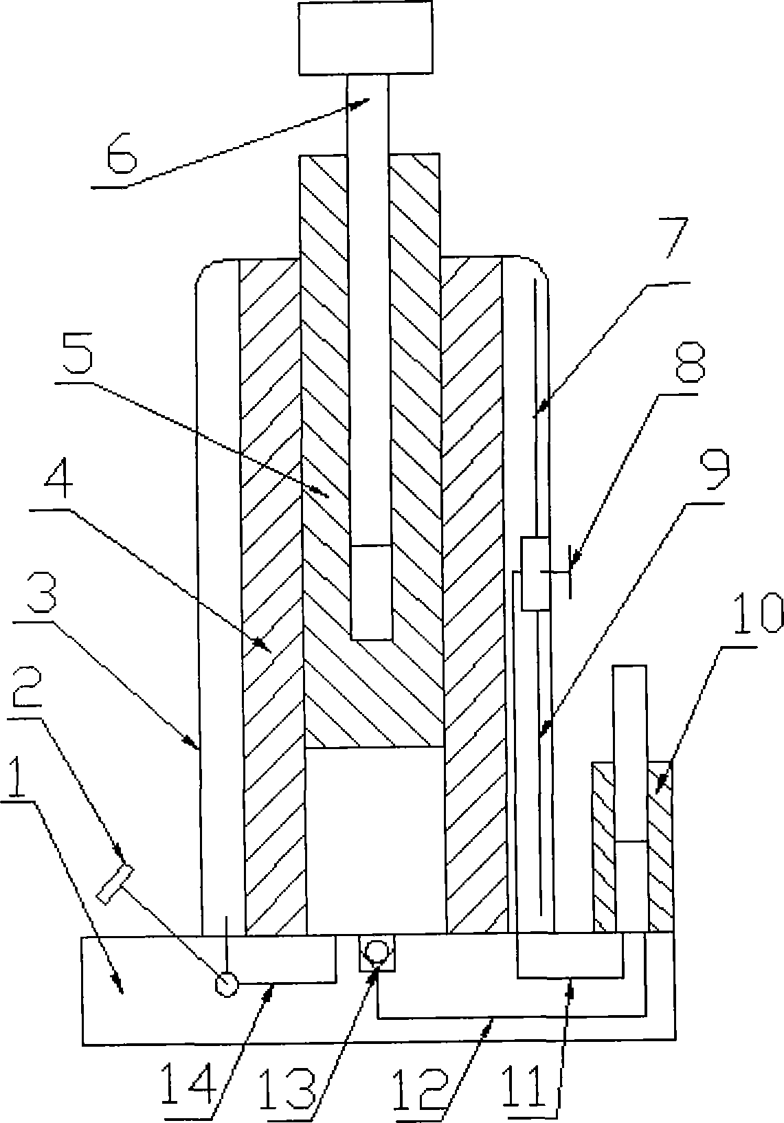
[0009] The total oil suction pipe (11), high-pressure passage (12), and oil discharge passage (14) in the present invention are pre-set on the base (1), and the one-way valve (13) is arranged at the outlet end of the high-pressure passage (12), Install and fix the piston (4) on the base (1), align the center of the piston (4) with the one-way valve (13), and install a three-way valve (8) in the middle of the oil tank (3) , the conversion handle of the three-way valve (8) is outside the fuel tank (3), connect the oil suction pipe A (7) and the oil suction pipe B (9) to the three-way valve (8) respectively, and make the oil pipe A (7) and The ports of the oil suction pipe B (9) are respectively placed at the bottom and top of the fuel tank (3), and the two ends of the main oil suction pipe (11) are respectively connected to one of the channels of the manual hydraulic pump (10) and the three-way valve (8) , the piston (5) is installed in the cylinder of the piston cylinder (4), t...


PUM


Abstract

The invention discloses a hydraulic jack. An oil suction header pipe, a high pressure passage and an oil release passage are pre-arranged on a base; a one-way valve is arranged at the outlet of the high pressure passage; a piston cylinder is fixedly arranged on the base; the central part of the piston cylinder is aligned with the one-way valve; the middle of an oil tank is provided with a three-way valve; a switching handle of the three-way valve is positioned outside the oil tank; an oil suction pipe A and an oil suction pipe B are connected with the three-way valve; ports of the oil suction pipe A and the oil suction pipe B are positioned on the bottom and the top of the oil tank; two ends of the oil suction header pipe are communicated with a manual hydraulic pump and one passage of the three-way valve; a piston is arranged in a cylinder of the piston cylinder; an adjusting screw is arranged in the middle of the piston; and the oil release valve is arranged in the middle of the oil release passage on the base.

Description

technical field [0001] The invention relates to a jack, in particular to a hydraulic jack, and belongs to the technical field of hydraulic jacks. Background technique [0002] At present, the general hydraulic jack is composed of oil suction oil passage, oil pressure oil passage, oil discharge oil passage, base, piston cylinder, and manual plunger pump. The one-way ball valve opens and the oil pressure one-way valve closes. At this time, the oil is sucked into the pump from the oil storage tank. When the plunger is down, the oil suction one-way valve is closed and the oil pressure one-way valve is opened. The channel enters the high-pressure chamber and pushes the piston upward to achieve the purpose of lifting. This kind of hydraulic jack is widely used because of its delicate structure, convenient handling and simple maintenance. However, in some other occasions, it is necessary to turn the jack upside down or lay it flat Use, at this time, due to the structural reasons o...

Claims


Application Information

Patent Timeline
Patent Type & Authority Applications(China)
IPC IPC(8): B66F3/24B66F3/25B66F3/26
Inventor 王欣
Owner 王欣
Why Eureka
Try Eureka