
Grinding head spindle assembly for ball grinder with hollow cooling and flushing structure

A spindle and sphere technology, applied in the field of the grinding head spindle assembly of a ball grinder, can solve the problems of poor surface quality of grinding spheres, inability to achieve cooling and flushing effect, and single cooling liquid supply method, and improve machining accuracy and stability. , Solve the effect of thermal stability and poor grinding surface quality

Inactive Publication Date: 2011-12-21
孟灵杰
View PDF4 Cites 8 Cited by
  • Summary
  • Abstract
  • Description
  • Claims
  • Application Information

AI Technical Summary

Problems solved by technology

The existing main shaft structure only simply lubricates the bearings, but does not take corresponding measures for the thermal deformation of the main shaft parts caused by the heat generated by other transmission parts, resulting in a short service life of the main shaft bearings and a high failure rate
Second, the coolant supply mode is single, the flushing effect is not obvious, and the surface quality of the grinding ball is poor
The existing liquid supply method is to spray from the outside to the grinding area, but because the peripheral speed of the grinding disc used for ball grinding is relatively high, a thin layer of air around the surface also rotates at a high speed with the grinding disc, forming a stream. The high-speed airflow prevents the coolant from entering the grinding area, and the effect of cooling and flushing cannot actually be achieved, resulting in poor surface quality of the grinding ball

Method used


Image

  • Grinding head spindle assembly for ball grinder with hollow cooling and flushing structure
  • Grinding head spindle assembly for ball grinder with hollow cooling and flushing structure
  • Grinding head spindle assembly for ball grinder with hollow cooling and flushing structure

Examples


Embodiment Construction

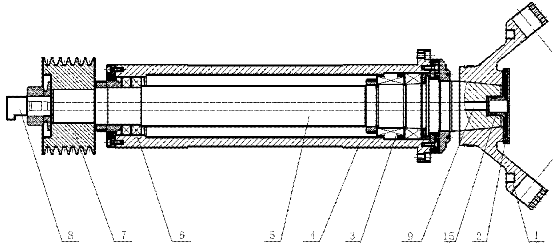
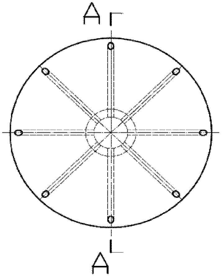
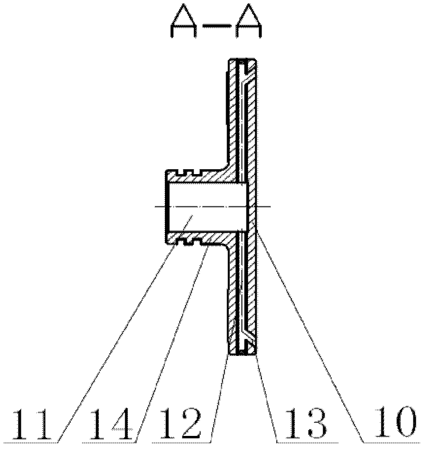
[0012] Attached below figure 1 , 2 , 3 describe an embodiment of the present invention.

[0013] A ball grinder grinding head spindle assembly with a hollow cooling and flushing structure, comprising a grinding disc 1, a bearing I3, a bearing II6, a sleeve 4, a main shaft 5 and a pulley 7, the main shaft 5 is installed on the In the sleeve 4, the belt pulley 7 and the grinding disc 1 are respectively fixed on the two ends of the main shaft 5. The center of the main shaft 5 has an axial through hole 9, the rear end of the main shaft 5 is connected with a rotary joint 8, the front end of the main shaft 5 is connected with a hydraulic spray disc 2, and the hydraulic spray disc 2 is fixed in the center of the inner cavity of the grinding disc 1, and The liquid inlet port of the hydraulic injection disc 2 communicates with the front end of the axial through hole 9 , and the inner chamber of the rotary joint 8 communicates with the rear end of the axial through hole 9 .

[0014] ...


PUM


Abstract

The invention discloses a grinding head spindle assembly provided with a hollow cooling and washing structure of a ball grinding machine. The grinding head spindle assembly comprises a grinding disc 1, a bearing I3, a bearing II 6, a sleeve 4, a spindle 5 and a belt pulley 7, wherein the spindle 5 is arranged in the middle of the sleeve through the bearing I3 and the bearing II6, the belt pulley 7 and the grinding disc 1 are fixed at two ends of the spindle 5 respectively, an axial through hole 9 is arranged at the center of the spindle 5, the rear end of the spindle 5 is connected with a rotary connector 8, the front end of the spindle 5 is connected with a liquid spraying and pressing plate 2, the liquid spraying and pressing plate 2 is fixed at the center of the cavity of the grinding disc, a liquid inlet of the liquid spraying and pressing plate 2 is communicated with the front end of the axial through hole 9, and the cavity of the rotary connector 8 is communicated with the rear end of the axial through hole 9. The grinding head spindle assembly disclosed by the invention overcomes the deficiencies of poor heat stability of the spindle and single cooling liquid feeding method, improves the precision and stability of the machine, and is mainly applicable to grinding machines used for grinding symmetrical balls in the ball valve industry.

Description

technical field [0001] The invention belongs to the technical field of spherical grinding machines, and in particular relates to a grinding head spindle assembly of a spherical grinding machine with a hollow cooling and flushing structure. Background technique [0002] The accuracy of the sphericity and surface roughness of the sphere processed by the existing sphere grinding machine cannot meet the design requirements. Tracing it to its cause, there are two main disadvantages. One is that the thermal stability of the main shaft part is poor, and the precision error of the grinding sphere is large. The thermal stability of spindle components includes temperature stability and precision stability. The existing main shaft structure only simply lubricates the bearings, but does not take corresponding measures for the thermal deformation of the main shaft parts caused by the heat generated by other transmission parts, resulting in a short service life of the main shaft bearings...

Claims


Application Information

Patent Timeline
IPC IPC(8): B24B41/04B24B55/02B24B11/02
Inventor 孟灵杰权晓刚张宏强
Owner 孟灵杰
Learn More