
Follower rest device for horizontal gantry lathe

A technology for horizontal lathes and tool holders, which is applied in the direction of auxiliary devices, turning equipment, tool holder accessories, etc., can solve the problems affecting the machining accuracy and application range of lathes, unfavorable thick and long axis machining, and limitation of machining capacity, etc., to achieve It is convenient for mass production and promotion, easy to operate and maintain, and the effect of increasing the diameter range

Inactive Publication Date: 2013-12-18
SHANDONG HONGKANG MACHINERY MFG
View PDF7 Cites 3 Cited by
  • Summary
  • Abstract
  • Description
  • Claims
  • Application Information

AI Technical Summary

Problems solved by technology

[0002] In the traditional ordinary lathe, the tool rest is fixed on the small pallet, and then the small pallet, the horizontal pallet, and the large pallet are superimposed on the bed guide rails layer by layer, so that the maximum machining diameter on the tool post is only the maximum machining diameter on the bed. slightly more than half of that, which is not conducive to the processing of thick long axis
The current mobile gantry-type CNC lathes can increase the diameter range of the processed bar, but the processing capacity is limited when processing long-axis parts, especially its poor stability, which affects the processing accuracy and scope of application of the lathe.

Method used


Image

  • Follower rest device for horizontal gantry lathe
  • Follower rest device for horizontal gantry lathe
  • Follower rest device for horizontal gantry lathe

Examples


Embodiment Construction

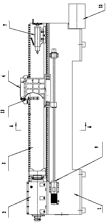
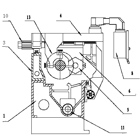
[0011] from figure 1 is a structural schematic diagram of the present invention and figure 2 It can be seen from the A-A sectional view that the present invention includes a gantry frame 4 and a heel tool rest 13, the gantry frame 4 is installed on two horizontal guide rails of the front of the bed 1 and the rear support wall 3, and the rear support wall 3 is behind the bed 1. A gantry feeding device 9 is installed between the gantry frame 4 and the bed 1 , and the gantry feeding device 9 drives the gantry frame 4 to move laterally along the horizontal guide rail on the bed 1 . The gantry horizontal lathe of the present invention mainly includes a bed 1, a headstock 2, a rear support wall 3, a gantry frame 4, a tool rest 5, a small pallet 6, a tailstock 7, an electric control part 8, a gantry feed device 9, Tool rest feeding device 10, spiral chip removal device 11, waste material box 12, follower tool rest 13 and other parts. The installation position of headstock 2 and ta...


PUM


Abstract

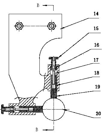
The invention discloses a follower rest device for a horizontal gantry lathe. The follower rest device comprises a gantry. A follower rest is installed on one side of the gantry. A follower rest seat is installed on the side surface of the gantry in a suspended way. The upper part of the follower rest seat is fixed with the gantry. A follower rest supporting device which consist of two groups of rotating handles, positioning sleeves, screws, guide columns and ejection columns is installed at the lower part of the follower rest seat in a direction perpendicular to the axis of a workpiece. The follower rest device for the horizontal gantry lathe has the advantages that not only can the range of the diameter of machined bars be increased, but also the processing stability and the machining accuracy of long shaft parts are increased, and the application scope of the lathe is increased.

Description

technical field [0001] The invention belongs to the technical field of metal cutting machine tools, and in particular relates to a tool rest device for a gantry horizontal lathe. Background technique [0002] In the traditional ordinary lathe, the tool rest is fixed on the small pallet, and then the small pallet, the horizontal pallet, and the large pallet are superimposed on the bed guide rails layer by layer, so that the maximum machining diameter on the tool post is only the maximum machining diameter on the bed. A little more than half of that is not conducive to the processing of thick long axis. The current mobile gantry-type CNC lathes can increase the diameter range of the processed bar, but the processing capacity is limited when processing long-axis parts, especially its poor stability, which affects the processing accuracy and scope of application of the lathe. Contents of the invention [0003] The purpose of the present invention is to solve the above-mention...

Claims


Application Information

Patent Timeline
IPC IPC(8): B23Q1/76B23B25/00
Inventor 康凤明朱洪军朱岱坤
Owner SHANDONG HONGKANG MACHINERY MFG
Learn More