A high-power LED drive power cooling device based on carbon nanotubes
An LED driver and carbon nanotube technology, applied in the power supply field, can solve the problems of insufficient thermal conductivity of materials, high cost, high density, etc., and achieve the effects of light weight, reduced lamp weight, and good heat transfer performance.
- Summary
- Abstract
- Description
- Claims
- Application Information
AI Technical Summary
Problems solved by technology
Method used
Image
Examples
Embodiment 1
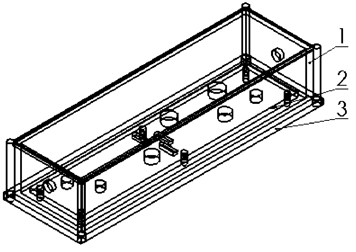
[0026] Specific embodiments of the present invention As shown in the accompanying drawings, a high-power LED drive power heat dissipation device based on carbon nanotubes, the heat sink 3 and the back of the PCB board 2 are connected by fasteners.
[0027] The heat sink 3 also includes a heat sink 303 at the bottom of the heat sink; the inside of the heat sink is coated with two layers of heat dissipation material, the layer close to the PCB board is thermally conductive adhesive, and the layer below the thermally conductive adhesive is carbon nanotubes .
[0028] The heat-conducting adhesive is closely combined with the PCB board 2 and the carbon nanotubes, which can better conduct heat from the PCB board to the carbon nanotubes.
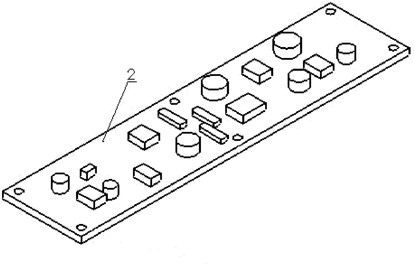
[0029] When the power supply is working, a large number of electronic components are arranged on the PCB board 2 to generate a large amount of waste heat, which will be transferred from the PCB board 2 to the heat dissipation groove 303 at the bott...
Embodiment 2
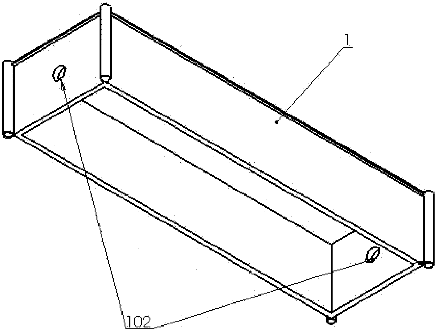
[0031] Specific embodiments of the present invention As shown in the accompanying drawings, a high-power LED drive power cooling device based on carbon nanotubes includes a protective cover 1, a PCB board 2, and a radiator 3; the radiator 3 and the back of the PCB board 2 The connection is made through fasteners, and the protective cover 1 is connected with the radiator 3 through fasteners, and completely covers the PCB board 2 .
[0032] The heat sink 3 also includes a heat sink 303 at the bottom of the heat sink; the inside of the heat sink is coated with two layers of heat dissipation material, the layer close to the PCB board is thermally conductive adhesive, and the layer below the thermally conductive adhesive is carbon nanotubes .
[0033] The heat-conducting adhesive is closely combined with the PCB board 2 and the carbon nanotubes, which can better conduct heat from the PCB board to the carbon nanotubes.
[0034] When the power supply is working, a large number of el...
Embodiment 3
[0036] Specific embodiments of the present invention As shown in the accompanying drawings, a high-power LED drive power cooling device based on carbon nanotubes includes a protective cover 1, a PCB board 2, and a radiator 3; the radiator 3 and the back of the PCB board 2 The connection is made through fasteners, and the protective cover 1 is connected with the radiator 3 through fasteners, and completely covers the PCB board 2 .
[0037] There is also a wire outlet 102 on both sides of the protective cover 1 , such as a circuit on the PCB board, which can be introduced and exported from the outlet 102 .
[0038] The heat sink 3 also includes a heat sink 303 at the bottom of the heat sink; the inside of the heat sink is coated with two layers of heat dissipation material, the layer close to the PCB board is thermally conductive adhesive, and the layer below the thermally conductive adhesive is carbon nanotubes .
[0039] The heat-conducting adhesive is closely combined with t...
PUM
 Abstract
Description
Claims
Application Information
 - R&D Engineer
- R&D Manager
- IP Professional
- Industry Leading Data Capabilities
- Powerful AI technology
- Patent DNA Extraction
Browse by: Latest US Patents, China's latest patents, Technical Efficacy Thesaurus, Application Domain, Technology Topic, Popular Technical Reports.
© 2024 PatSnap. All rights reserved.Legal|Privacy policy|Modern Slavery Act Transparency Statement|Sitemap|About US| Contact US: help@patsnap.com


