
An integrated microphone bias voltage control method and bias voltage generation circuit

A technology for bias voltage and circuit generation, applied in control/regulating systems, adjusting electrical variables, instruments, etc., can solve the problems of microphone circuit bias voltage fluctuation and increase the complexity of energy-consuming circuits, so as to reduce fluctuation, The effect of reducing energy consumption and saving production costs

Active Publication Date: 2011-12-07
SHANDONG GETTOP ACOUSTIC
View PDF6 Cites 9 Cited by
  • Summary
  • Abstract
  • Description
  • Claims
  • Application Information

AI Technical Summary

Problems solved by technology

[0013] In view of the above defects in the prior art, the present invention strives to solve the problem that the bias voltage in the microphone circuit fluctuates with the change of the operating point, while avoiding the increase of energy consumption and circuit complexity

Method used


Image

  • An integrated microphone bias voltage control method and bias voltage generation circuit
  • An integrated microphone bias voltage control method and bias voltage generation circuit
  • An integrated microphone bias voltage control method and bias voltage generation circuit

Examples


Embodiment Construction

[0038] The control idea of ​​the microphone bias voltage in the prior art is mainly to change the voltage and current curve by passively moving the starting point of the voltage and current curve by increasing the driving power of the charge pump. image 3 The medium current is the slope of the curve near 0 point, the effect is limited, and the energy cost of control is also high. The present invention proposes a different control idea.

[0039] Through many years of practice, the inventor found that if the output voltage of the bias voltage generation circuit can be controlled so that the output power of the charge pump can not be changed, the image 3 The change of the slope of the curve near the point where the middle current is 0 will effectively improve the stability of the bias voltage. Therefore, the present invention proposes such a control idea and control method: control the relationship between the output voltage and current of the bias voltage generating circuit, s...


PUM


Abstract

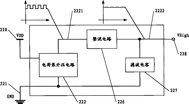
The invention discloses an integrated microphone offset voltage control method and an offset circuit. The method is implemented based on the CMOS (complementary metal-oxide-semiconductor) or BiCMOS (bipolar complementary metal oxide semiconductor) integrated circuit production process, and is applied to an offset voltage generating circuit of a silicon microphone which comprises a charge pump booster circuit, a rectifier circuits and a filter circuits. According to the method, the relationship between output voltages and input currents of the offset voltage generating circuit is controlled, so that the circuit is within a neighboring region with zero current, the input currents of output nodes of the circuit are increased with the increase of output voltages, and the increasing slope rises rapidly with the increase in voltage. The circuit is implemented by connecting a compensation circuit in parallel between the output terminal and the ground terminal of the rectifier circuit; and the compensation circuit has the following functions: in the region of almost zero current and close to the voltage of offset voltage working points of the microphone, the input currents of the output nodes are increased with the increase of voltages applied to the two ends of the compensation circuit, and the current increase rate is higher than the voltage increase rate.

Description

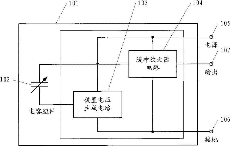
technical field [0001] The invention relates to a microphone of an electronic sound collection device, more precisely, to an integrated method for controlling the bias voltage of the microphone and a voltage bias circuit of the microphone. Background technique [0002] In condenser microphones, especially condenser silicon microphones, an additional circuit is required to generate a high voltage bias from the microphone power supply for proper microphone sensitivity. The schematic diagram of a typical silicon microphone is as follows: figure 1 As shown, the silicon microphone includes: a housing 101 , a capacitor assembly 102 composed of upper and lower plates, a bias voltage generation circuit 103 and a microphone buffer amplifier circuit 104 . The power supply 105 and the "ground" terminal 106 are respectively connected to the buffer amplifier circuit 104 and the bias voltage generating circuit 103 to provide the two with an operating voltage; the bias voltage generating ...

Claims


Application Information

Patent Timeline
IPC IPC(8): H04R3/02G05F3/16
Inventor 杨少军
Owner SHANDONG GETTOP ACOUSTIC
Learn More