
An internal reaming tool based on continuous automatic chip removal for blind deep holes

A technology for reaming tools and deep holes, which is applied to lathe tools, boring/drilling, drilling/drilling equipment, etc. It can solve the problems of small vibration, achieve complete functions, uniform chip breaking, and reduce Effect of Surface Roughness

Inactive Publication Date: 2011-11-30
ZHONGBEI UNIV
View PDF2 Cites 17 Cited by
  • Summary
  • Abstract
  • Description
  • Claims
  • Application Information

AI Technical Summary

Problems solved by technology

At present, there is no internal reaming tool with small vibration, accurate guidance and profiling processing of complex special-shaped holes such as conical surfaces, cylindrical surfaces, and spherical surfaces.

Method used


Image

  • An internal reaming tool based on continuous automatic chip removal for blind deep holes
  • An internal reaming tool based on continuous automatic chip removal for blind deep holes
  • An internal reaming tool based on continuous automatic chip removal for blind deep holes

Examples


Embodiment Construction

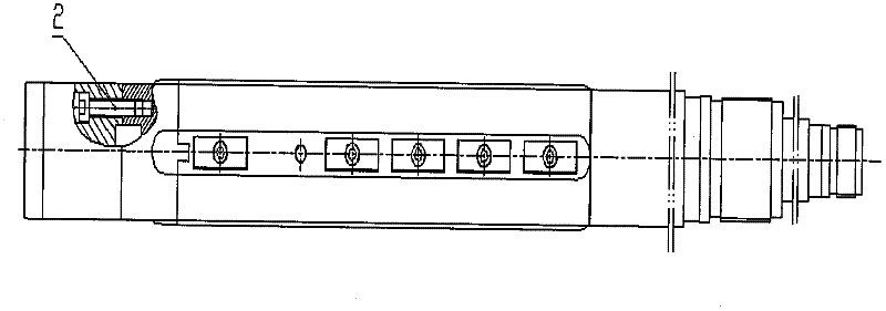
[0021] As shown in the drawings, the present invention of the present invention is characterized in that: the pull rod support sleeve 16 is connected with the push-pull rod 20 through the countersunk head screw 17, and the push-pull rod 20 is connected with the guide rail 10 through the conical pin 14 to form a push-pull mechanism; The pin 12 is connected with the boring tool body 15 through interference fit, and plays the role of preventing the guide rail 10 from rotating and limiting during the sliding process; the diamond-shaped coating machine clip blade 3 is fixed on the small boring tool body 5 with a specific countersunk head screw 4 Composition of the mobile tool rest mechanism; under the left and right movement of the push-pull rod 20, the small boring tool body 5 is driven to slide in the chute of the guide rail 10 to realize the radial and free telescopic movement of the entire mobile tool rest mechanism; the end cover 7 uses two countersunk screws 6 It is fixed on t...


PUM


Abstract

The invention discloses an inner chambering cutter based on the continuous automatic rear chip removal of a blind deep hole, aiming to provide a special inner chambering cutter which is more favourable for processing special parts with irregular and complex curve, such as a conical surface, a sphere, a cylindrical surface and the like in the blind deep hole, the middle of each special part is big, and two ends of the part are small. The inner chambering cutter comprises a push-pull mechanism, a movable tool rest mechanism, an end cover and a cutter body, wherein the push-pull mechanism is formed by connecting a push-pull rod and a guide rail via a taper pin; a diamond coating machine clip blade is fixed on a small boring cutter body by a special sunk screw to form a movable tool rest mechanism; when the push-pull mechanism moves left and right, slope movement is carried out on the tool rest mechanism to realize the purpose that the tool rest mechanism radially moves; and the end cover is fixed on the front end of the boring cutter support body by two bolts to prevent a cutting fluid and cuttings from flowing into the inner cavity of a boring rod. The cutter body is composed of the boring cutter support body, a middle boring cutter body and a boring cutter body. The chip removal mode disclosed by the invention is rear chip removal in the external chip removal.

Description

technical field [0001] The invention relates to the technical field of deep hole machining, in particular to an internal reaming tool based on continuous automatic chip removal for blind deep holes. Background technique [0002] Deep hole processing is a difficult processing technology in the machinery industry. It is processed by drilling first, then expanding, and finally finishing. As far as hole reaming is concerned, the traditional reaming method is limited to the processing of equal-diameter holes or small holes in the middle of the large end, which can be solved by step reaming cutter or conventional deep hole reaming drills of different types. When the depth of the deep hole exceeds dozens or even hundreds of times of the hole diameter, it is extremely difficult to remove chips, the cutting vibration is large, the guidance is poor, and it is easy to deviate, not to mention some mechanical industries such as aerospace, automobile manufacturing, and light industry mold...

Claims


Application Information

Patent Timeline
IPC IPC(8): B23B27/16B23B29/02B23B41/02
Inventor 庞俊忠
Owner ZHONGBEI UNIV
Learn More