Microchannel heat exchanger and manufacturing method thereof
A technology of micro-channel heat exchanger and intermediate channel, which is applied in the field of micro-channel heat exchanger and its production, and can solve the problem of aggravated single-arm suspension structure instability, unbalanced flow of heat-exchanging working fluid, and stress on distribution pipe 9 Inhomogeneity and other problems, to achieve the effect of simple and reasonable structure, low production cost, and uniform distribution
- Summary
- Abstract
- Description
- Claims
- Application Information
AI Technical Summary
Problems solved by technology
Method used
Image
Examples
Embodiment 1
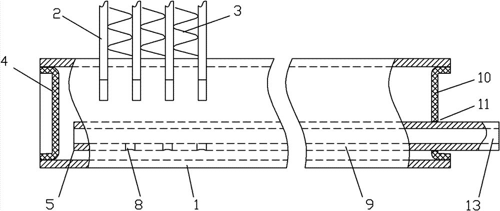
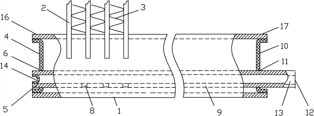
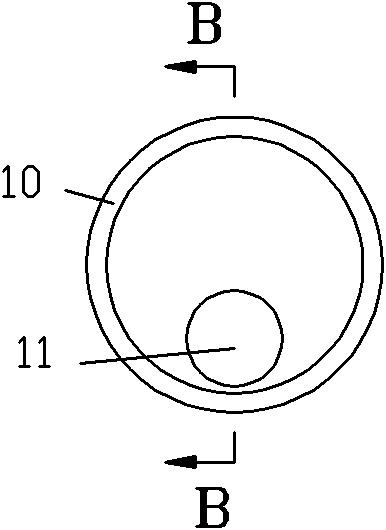
[0036] see Figure 2-Figure 4 , figure 2 The microchannel heat exchanger in it includes a header 1, a flat tube 2, fins 3, a first end plate 4, a distribution pipe 9, a second end plate 10, a distribution hole 8 arranged on the distribution pipe 9, and a The assembly hole 6 on the first end plate 4, the inlet 12 on the distribution pipe 9, the first port 5 of the distribution pipe 9, the second port 13 of the distribution pipe 9, and the positioning hole 11 arranged on the second end plate 10 , the first end 16 of the header 1 , and the second end 17 of the header 1 .
[0037] The flat tube 2 is provided with an intermediate channel, the fins 3 are arranged between the flat tubes 2, the distribution pipe 9 is provided in the collecting pipe 1, and the side wall of the distribution pipe 9 is provided with an inner cavity that can lead to the collecting pipe 1 The dispensing hole 8.
[0038] The first port 5 of the distribution pipe 9 passes through the assembly hole 6 on th...
Embodiment 2
[0059] Embodiment 2 of the present invention differs from Embodiment 1 in that, as Figure 5-Figure 6 As shown, the header 1 of the second embodiment is also provided with an internal bracket 7 for supporting the distribution pipe 9, such as Figure 6 As shown, the upper part of the inner bracket 7 is curved, and the lower part is connected to the header 1. In this embodiment, the inner bracket 7 and the tube wall of the header 1 are fixed by welding. In this way, the inner bracket 7 can support the distribution pipe 9, further reducing the vibration of the distribution pipe 9. Brazing material can also be applied between the internal bracket 7 and the distribution pipe 9, and then through integral welding, the two can be connected and fixed together more stably, and the effect of reducing vibration and noise is better.
[0060] Another advantage of adopting the inner bracket 7 is that in the manufacturing step d, when the distribution pipe is stretched forward, the inner bra...
Embodiment 3
[0063] Embodiment 3 of the present invention differs from Embodiment 2 in that, as Figure 7 As shown, the positioning protrusion 27 in the collector 7 of the third embodiment is not connected to the collector by welding, but formed in the collector by mechanical extrusion. Likewise, the positioning protrusion 27 can support the distribution pipe 9 to reduce vibration. The advantage of using the positioning protrusion 27 in the third embodiment is that it can be processed and formed before heating and brazing. In manufacturing step d, the distribution tube is pressed against the positioning protrusion 27, because the positioning protrusion 27 is integral with the header and does not affect its quality. However, in the second embodiment, before heating and brazing, the internal bracket 7 has not been melted and fixed with the collector. Of course, in this embodiment, the positioning protrusion 27 also has the positioning function as in the second embodiment.
[0064] See emb...
PUM
 Abstract
Description
Claims
Application Information
 - R&D
- Intellectual Property
- Life Sciences
- Materials
- Tech Scout
- Unparalleled Data Quality
- Higher Quality Content
- 60% Fewer Hallucinations
Browse by: Latest US Patents, China's latest patents, Technical Efficacy Thesaurus, Application Domain, Technology Topic, Popular Technical Reports.
© 2025 PatSnap. All rights reserved.Legal|Privacy policy|Modern Slavery Act Transparency Statement|Sitemap|About US| Contact US: help@patsnap.com


