Controlled exhaust backpressure valve for engine

An exhaust back pressure, engine technology, applied in engine control, machine/engine, mechanical equipment, etc., can solve problems such as unsatisfactory, low internal EGR rate, unreachable, etc., to increase temperature, promote CAI combustion, and avoid hold-up. dead effect

Inactive Publication Date: 2011-11-23
TIANJIN UNIV +1
View PDF7 Cites 4 Cited by
  • Summary
  • Abstract
  • Description
  • Claims
  • Application Information

AI Technical Summary

Problems solved by technology

[0005] For the control strategy of internal exhaust gas recirculation (i-EGR), the VVT ​​of the existing direct injection engine technology platform of Changan Automobile Company adopts the valve control strategy of the positive overlap angle of the intake and exhaust valves, but the maximum internal EGR rate is 29%. It cannot meet the minimum internal EGR rate requirement of about 40% required to realize CAI combustion, and cannot realize CAI combustion
In addition, for the direct injection engine, by increasing the overlapping angle of the intake and exhaust valves, although a certain amount of internal residual exhaust gas can be obtained, it is limited by the cam profile and VVT change angle (30oCA VVT phase adjustment range) , relying solely on the change of the intake and exhaust valve phases, a sufficient proportion of internal residual exhaust gas cannot be obtained, so the conditions required for CAI combustion cannot be achieved
In the internal exhaust gas recirculation system of the prior art, the exhaust gas discharge pressure and exhaust gas discharge volume of the engine are fixed values, which cannot be changed according to the actual combustion demand, so the improvement of the combustion effect is relatively small

Method used


Image

  • Controlled exhaust backpressure valve for engine
  • Controlled exhaust backpressure valve for engine
  • Controlled exhaust backpressure valve for engine

Examples


Embodiment Construction

[0023] The present invention will be described in detail below with reference to the drawings and embodiments.

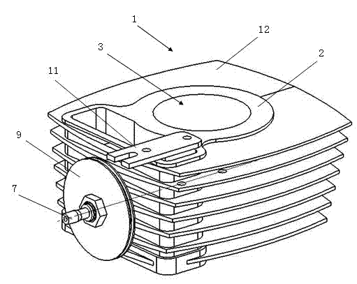
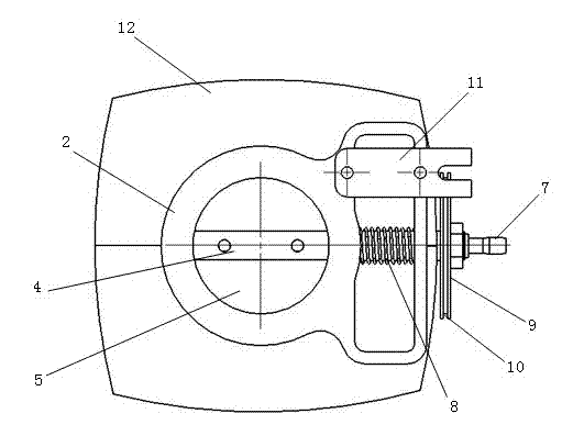
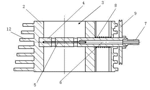
[0024] figure 1 It is a schematic diagram of the structure of the controllable exhaust back pressure valve for the engine of the present invention; figure 2 It is a top view of the controllable exhaust back pressure valve for the engine of the present invention; image 3 It is a longitudinal sectional view of the controllable exhaust back pressure valve for the engine of the present invention.

[0025] Such as figure 1 As shown, in the controllable exhaust back pressure valve 1 for an engine of the present invention, the exhaust back pressure valve 1 is connected to the exhaust manifold of the engine, and is connected in series in the exhaust pipe of the engine, and includes: a body 2, which constitutes The main part of the exhaust back pressure valve, which carries other components of the exhaust back pressure valve; the exhaust passage 3, which penetrates the body of ...


PUM


Abstract

The invention discloses a controlled exhaust backpressure valve for an engine. The exhaust backpressure valve is connected with an exhaust header pipe of the engine and connected in series in an exhaust pipeline of the engine; the exhaust backpressure valve comprises a body, an exhaust passage, a door shaft and a door panel, wherein one end of the body is inserted into and vertically passes through the side wall of the exhaust passage, and enters the interior of the exhaust passage; and the door panel is fixed with the door shaft and synchronously rotates together with the door shaft, the shape and the size of the door panel correspond to those of the cross section of the exhaust passage, and the waste gas circulation area of the exhaust passage is regulated by changing the rotating angle of the door panel. By changing the rotating angles of the door shaft and the door panel, the pressure of waste gas can be controlled, the exhaust backpressure of the engine is improved, the internal residual waste gas is forcibly left in the cylinder, the quantity of the internal residual waste gas can be directly controlled, and the load of computer-aided instruction (CAI) combustion is further controlled; and by re-sucking the mixed gas in a heating cylinder through the waste gas, the temperature of the mixed gas is improved, so that implementation of the CAI combustion of the engine is promoted.

Description

Technical field [0001] The invention belongs to the technical field of engines, and in particular relates to a controllable exhaust back pressure for an engine that is connected in an engine exhaust pipe and controls the heat state of the mixed gas in the engine cylinder by changing the exhaust back pressure to realize CAI combustion. valve. Background technique [0002] Controlled Auto Ignition (CAI) of gasoline engine is a new combustion method that uses a mixture of compressed air and fuel (including recirculated exhaust gas) until it catches fire. Its essence is a combination of two combustion methods of diesel and gasoline engines. The improvement of the combustion method has high theoretical research value. It is a research hotspot in recent years, and it is also an increasingly mature combustion method. [0003] At present, the main methods to achieve CAI combustion at home and abroad are: direct intake heating, high compression ratio, use of fuels that are more prone to sp...

Claims


Application Information

Patent Timeline
IPC IPC(8): F02D9/04
Inventor 胡春明董亮亮侯圣智詹樟松刘斌于勇张巍
Owner TIANJIN UNIV
Why Eureka
Try Eureka