In-situ test system of strong laser beam quality

A technology of beam quality and in-situ detection, applied in photometry, optical radiation measurement, instruments, etc., can solve the problems of laser re-inspection and inability to detect with optical system, and achieve the effect of improving generation ability and anti-interference ability

Inactive Publication Date: 2011-11-16
CHANGCHUN UNIV OF SCI & TECH
View PDF5 Cites 9 Cited by
  • Summary
  • Abstract
  • Description
  • Claims
  • Application Information

AI Technical Summary

Problems solved by technology

When this method is used, the damage threshold of the detection device must also be considered. Therefore, when measuring high-energy lasers, the overall energy of the laser beam needs to be attenuated, resulting in most of the high-order components being filtered out, resulting in the use of 1 / e 2 Measurement error when energy determines beam width
In addition, the problem of in-situ detection of strong lasers is also a difficult problem. The previous detection methods can only be carried out on a single unit device of the laser, and it is impossible to detect the installed optical system or re-inspect the laser that has been used for a long time.

Method used


Image

  • In-situ test system of strong laser beam quality
  • In-situ test system of strong laser beam quality

Examples


Embodiment Construction

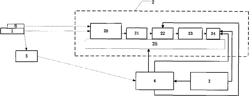
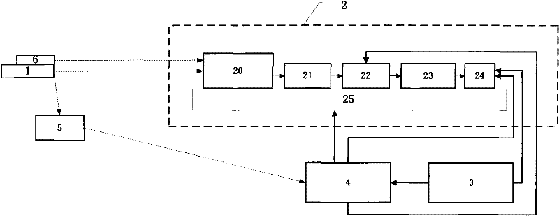
[0014] Strong laser beam quality in-situ detection system, such as figure 1 As shown, it is characterized in that the system consists of an optical measuring head unit 2 , an information processing computer 3 , a main control electric box 4 , a scattering receiving system 5 and an indicating laser 6 . The optical measuring head unit 2 is composed of an adaptive optical system 20 , a beam reduction system 21 , an electro-optic attenuation 22 , a microlens array 23 , a CCD 24 and a precise two-dimensional adjustment platform 25 .

[0015] The optical measuring head unit 2 is a receiving device used to measure the beam quality of a strong laser, and the adaptive optical system 20, the beam reduction system 21, the electro-optical attenuation 22, the microlens array 23 and the CCD 24 are all fixed on the precise two-dimensional adjustment platform 25 above, and sequentially coaxial mechanical connection; the laser beam emitted by the test object 1 first enters the adaptive optical...


PUM


Abstract

The invention, which belongs to the military laser test technology, provides an in-situ test system of a strong laser beam quality. The in-situ test system of the strong laser beam quality provided in the invention comprises: an optical measuring head unit, an information processing computer, a master-controlled electrical cabinet, a scattering receiving system and an indication laser. By using the system, the laser system beam quality of a plurality of platforms, such as a space-based laser system, a foundation, an airborne laser system, a shipbased laser system and vehicle-mounted, can be detected; an one-time rapid and comprehensive evaluation and an in-situ evaluation of the strong laser beam quality can be realized; generative capacity and anti-interference capability of the laser system can be raised. The system provides supports for the laser system to perform optimal efficiency.

Description

technical field [0001] The invention relates to an in-situ detection system for the beam quality of a strong laser, belonging to the technical field of laser testing. Background technique [0002] Since the laser was born more than 50 years ago, the key technology that must be solved is: the development of high-energy lasers with excellent performance to produce high-energy beams with high beam quality, and to provide energy for destroying, powering or processing targets. Core; develop a high-precision tracking and aiming system to make the launch telescope always track and aim at the target in flight, and make the spot lock on a fixed part of the target, that is, the laser converges on the aiming target with the minimum spot, maximum power density, and maximum energy concentration. point, thereby effectively destroying or destroying the target. Therefore, for the development, production and application of high-energy lasers, how to quickly, precisely and comprehensively ev...

Claims


Application Information

Patent Timeline
IPC IPC(8): G01J1/00G01J9/00
Inventor 王晓曼钟刚景文博姜会林刘树昌王彩霞段锦赵海丽刘鹏
Owner CHANGCHUN UNIV OF SCI & TECH
Why Eureka
Try Eureka