Water-saving non-return valve

A technology of check valve and spool, which is applied in the direction of lift valve, valve detail, control valve, etc., can solve the problems of increasing the complexity of the spool structure, increasing the space occupied by the check valve, and the long axial length of the spool, to achieve Good water-saving effect, shortened axial length, and reduced material consumption

Inactive Publication Date: 2012-11-14
XIAMEN SOLEX HIGH TECH IND CO LTD
View PDF2 Cites 0 Cited by
  • Summary
  • Abstract
  • Description
  • Claims
  • Application Information

AI Technical Summary

Problems solved by technology

It has the following disadvantages: because the one-way valve and the flow limiting device are separated independently, two brackets and two sealing rings are required, which not only wastes materials, but also increases the space occupied by the check valve.
Because the valve core needs to be sleeved with two sealing rings, one of which is used as a check valve for sealing, and the other sealing ring is used as a flow limiting device for adjustment, so there are the following deficiencies: 1. The axial length of the valve core Long, increase materials, increase manufacturing costs, and increase space occupation; 2. Set two sealing rings, increase materials, increase manufacturing costs; 3. Set two assembly grooves for sealing rings at the valve core to reduce the valve core. Strength, increase the complexity of the spool structure, and increase manufacturing costs

Method used


Image

  • Water-saving non-return valve
  • Water-saving non-return valve
  • Water-saving non-return valve

Examples


Embodiment Construction

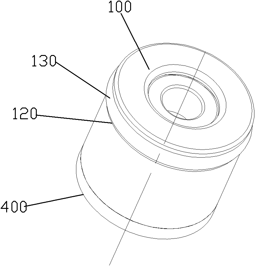
[0042] Please check Figure 1 to Figure 12 , A water-saving check valve, which includes a valve body 100, a valve core 200, a spring 300 and a valve seat 400.

[0043] The valve body 100 is provided with a water passage 110 penetrating through the top and bottom, and an annular assembly groove 120 outside the assembly groove 120, and a sealing ring 130 is sleeved at the assembly groove 120. The inner hole surface of the waterway 110 at least includes a sealing section 111, a water-saving section 112 and a fixed connection section 114 arranged in the forward direction of the water flow of the waterway 110. In this embodiment, the sealing section 111 is set as a conical surface section, and the inner diameter of the conical surface section increases continuously in the forward direction of the water flow, but it is not limited to this. According to needs, the sealing section 111 may also Set as a stepped hole (the sealing ring is connected to the stepped surface of the stepped hol...


PUM


Abstract

The invention discloses a water-saving non-return valve, which comprises a valve body, a valve core and a spring. A waterway (110) is formed inside the valve body (100); an inner hole face of the waterway (110) comprises a sealing section (111) and a water-saving section (112); a sealing ring (210) is sleeved outside the valve core (200); the spring (300) is pressed against the valve core (200), so that the valve core (200) is subjected to elastic force; if water in the waterway (110) positively flows and water pressure is higher than the elastic force, the valve core (200) moves to make the sealing ring (210) positioned on the water-saving section (112), and the sealing ring (210) radially deforms outwards due to the water pressure so as to reduce the sectional area at the periphery of the sealing ring (210) and between inner hole faces of the water-saving section (112); and if the water in the waterway (110) reversely flows and the water pressure is lower than the elastic force, thesealing ring (210) is positioned on the sealing section (111), and the sealing ring (210) seals an inner hole face of the sealing section (111). The invention has the advantages that: a non-return function and a water-saving function can be realized by a bracket and the sealing ring, the materials can be reduced, the manufacturing cost is reduced, the axial length of the valve core can be shortened, the occupied space is reduced, and the structure of the valve core can be simplified.

Description

Technical field [0001] The invention relates to a water-saving check valve. Background technique [0002] Existing water-saving check valves, such as: [0003] The utility model "Flow Regulating Check Valve" announced by the Chinese Patent Database on March 10, 2010, its patent number is CN200920137849.8. It includes a sleeve, a flow limiting device and a one-way valve. The one-way valve is sealed at the water outlet end of the sleeve, and the flow limiting device is arranged at the water inlet end of the sleeve; the flow limiting device includes a The water-saving sheet holder and the water-saving sheet sleeved in the water-saving sheet support are made of flexible material, which deforms with the water pressure to block the water passage holes of the water-saving sheet support. It has the following shortcomings: Because the one-way valve and the flow limiting device are separated independently, two brackets and two sealing rings are required, which not only wastes materials, bu...

Claims


Application Information

Patent Timeline
Patent Type & Authority Patents(China)
IPC IPC(8): F16K15/06F16K1/38F16K27/02F16K1/42
CPCF16K15/06F16K15/063
Inventor 黄祥刘梓光陈添育周华松
Owner XIAMEN SOLEX HIGH TECH IND CO LTD
Why Eureka
Try Eureka