
Numerical control system and control method based on dual-core architecture teamwork

A numerical control system and collaborative work technology, applied in the direction of total factory control, total factory control, electrical program control, etc., can solve the problems of low processing efficiency, system instability, CPU competition, etc., and achieve the goal of improving processing efficiency and fast transmission rate Effect

Inactive Publication Date: 2011-09-21
INST OF AUTOMATION CHINESE ACAD OF SCI
View PDF4 Cites 9 Cited by
  • Summary
  • Abstract
  • Description
  • Claims
  • Application Information

AI Technical Summary

Problems solved by technology

[0005] First, because the spatial geometric information of the front and rear small paths and the operating capacity of the motor are not considered, the machine tool will frequently accelerate and decelerate during the entire operation process, which not only reduces the processing efficiency, but also seriously affects the surface quality of the processed firmware.
[0006] Second, the workload of interpreting NC codes is large and requires a lot of computing time of the CPU. Therefore, online interpretation of NC codes will affect the processing time of the CPU for other modules, resulting in the inability of the machine tool to run at high speed.
[0007] Third, no matter how fast a single CPU is, its processing capacity is limited
Since the entire CNC system not only needs to control the operation of the machine tool quickly and in real time, but also needs to manage some slow devices, it is easy to cause CPU competition and other problems, resulting in system instability
[0008] Fourth, using a PC as a controller is expensive and not suitable for popular use

Method used


Image

  • Numerical control system and control method based on dual-core architecture teamwork
  • Numerical control system and control method based on dual-core architecture teamwork
  • Numerical control system and control method based on dual-core architecture teamwork

Examples


Embodiment Construction

[0045] The detailed problems involved in the technical solutions of the present invention will be described in detail below with reference to the accompanying drawings. It should be noted that the described embodiments are only intended to facilitate the understanding of the present invention without any limitation thereto.

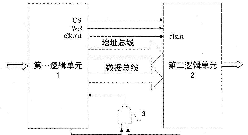
[0046] like figure 1The numerical control system structure based on the dual-core architecture is shown, including: a first logic unit 1, a second logic unit 2 and an AND gate 3, the first logic unit 1 and the second logic unit 2 are connected through an address bus and a data bus, and the An AND gate 3 is connected between an output end of the first logic unit 1 and an output end of the second logic unit 2; the input signal of the AND gate 3 is the control signal of the first logic unit 1 and the second logic unit 2 The output of the AND gate 3 is the synchronous control signal; when the machining starts, the first logic unit 1 first sets the control si...


PUM


Abstract

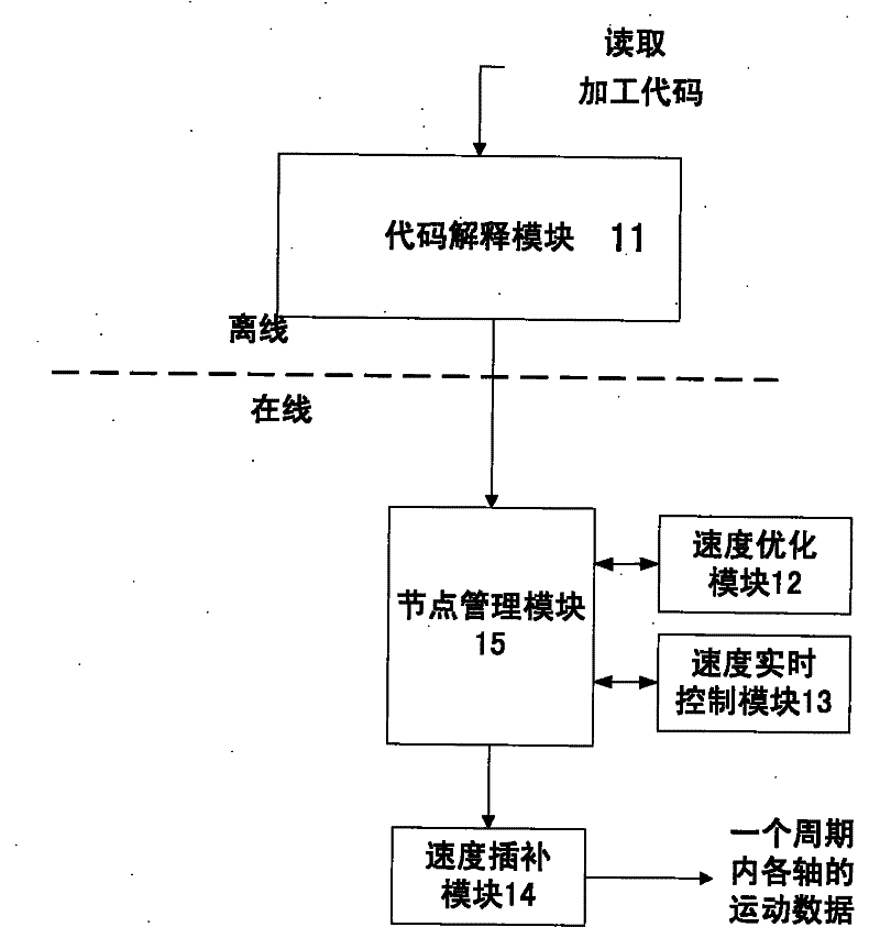
The invention discloses a numerical control system and control method based on dual-core architecture teamwork, which are characterized in that a first logic unit is connected with a second logic unit, and a conjunction gate is connected between the first logic unit and the second logic unit; the first logic unit sets control signals as high-level read-in processing codes, carries out interpretation on the codes, then manages data (interpreted by created forward-looking queue read codes) by using nodes, and after carrying out speed optimization, speed real-time control and speed interpolationon the data, outputting the motion data of each motor shaft in an interpolation cycle; the second logic unit outputs first feedback signals when the motion data of each motor shaft in a cycle is required; the first feedback signals and the control signals of the first logic unit pass through the conjunction gate, then synchronous control signals are outputted; after receiving the synchronous control signals, the first logic unit transmits the motion data of each motor shaft in a cycle to the second logic unit; and after receiving the motion data and carrying out computing on the motion data, the second logic unit outputs pulse signals for controlling motors.

Description

technical field [0001] The invention belongs to the technical field of numerical control of electromechanical integration, in particular to a high-speed numerical control system based on a dual-core framework that works cooperatively. Background technique [0002] The equipment manufacturing industry undertakes the important task of providing equipment for various industries in the national economy. Any country, for its own development and safety, will take the development of the equipment manufacturing industry as a national strategy. The "work machine" represented by CNC machine tools and CNC equipment is a typical representative of advanced machinery manufacturing equipment in the equipment manufacturing industry. [0003] The motion control system of automatic machining is a key part of the entire CNC system, which directly determines the performance, function, reliability and cost of machine tool equipment. [0004] The traditional CNC system's automatic processing mot...

Claims


Application Information

Patent Timeline
IPC IPC(8): G05B19/418
CPCY02P90/02
Inventor 王云宽黄为郑军
Owner INST OF AUTOMATION CHINESE ACAD OF SCI
Learn More