Waste gas flow guiding device of surface treatment groove

A technology of surface treatment and diversion device, applied in the direction of cells, electrolysis process, electrolysis components, etc., can solve the problems of inability to lift the gas collecting hood, damage the lifting crane, reduce production efficiency, etc., to avoid corrosion and damage to the crane, guarantee The effect of improving physical health and improving the drainage effect

Inactive Publication Date: 2012-11-28
PLASTIC ENG
View PDF1 Cites 0 Cited by
  • Summary
  • Abstract
  • Description
  • Claims
  • Application Information

AI Technical Summary

Problems solved by technology

However, the exhaust gas extraction device disclosed in this patent also has the following disadvantages: 1. The hoisting crane is located inside the gas collection hood, and the exhaust gas will still corrode and damage the hoisting crane; When moving to the electroplating tank of the corresponding process, it takes time to connect the gas collecting hood to the electroplating tank, and when it is necessary to move to the next process, it takes time to disconnect the gas collecting hood and the electroplating tank. The production efficiency is greatly reduced; 3; the gas collecting hood cannot be raised and lowered in the vertical direction, which affects the workers' handling or monitoring of the workpieces in the electroplating tank of the corresponding process

Method used


Image

  • Waste gas flow guiding device of surface treatment groove
  • Waste gas flow guiding device of surface treatment groove
  • Waste gas flow guiding device of surface treatment groove

Examples


Embodiment Construction

[0024] Below in conjunction with accompanying drawing, the present invention will be further described:

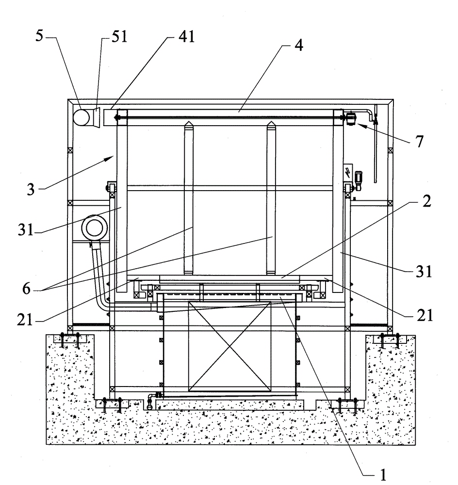
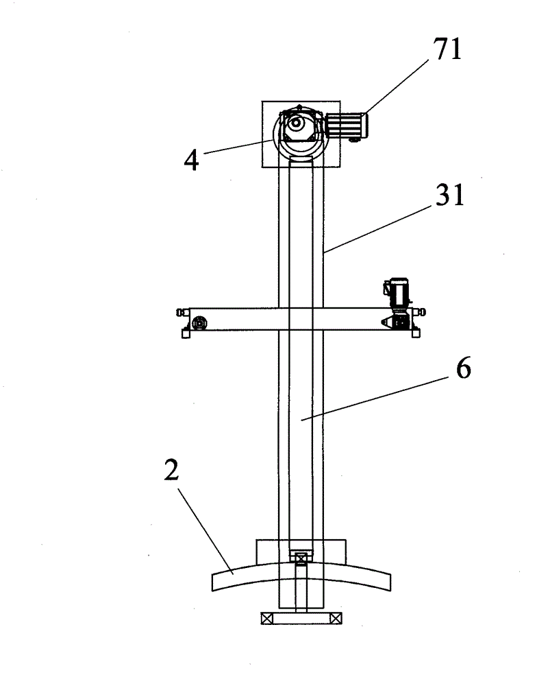
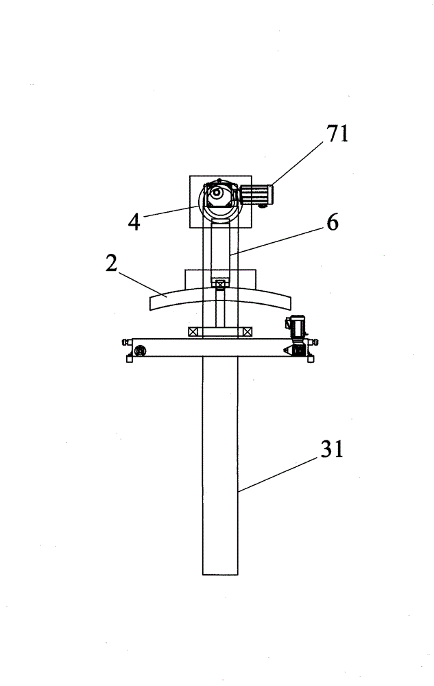
[0025] Such as Figure 1 to Figure 4 As shown, the waste gas guide device for surface treatment tanks of the present invention has a structure as follows: it includes several coating tanks 1, a crane that is movably positioned above the coating tanks 1, a main exhaust pipe 5 connected with an exhaust fan, and a PLC Control system, flow guide cover 2, telescopic throat pipe 6, frame body 3 installed in the crane, exhaust branch pipe 4 installed in frame body 3, and cover body lifting drive mechanism 7 for driving the flow guide cover 2 to move up and down The shroud 2 is located below the exhaust branch pipe 4 and can be moved with the crane above the plating tank 1, the telescopic throat pipe 6 is connected between the shroud 2 and the exhaust branch pipe 4, and the cover lifting drive mechanism 7 is driven to connect the shroud 2; the position of the main exhaust duct 5 ...


PUM


Abstract

The invention relates to the technical field of surface treatment equipment, and in particular relates to a waste gas flow guiding device of a surface treatment groove. The waste gas flow guiding device comprises a plurality of plating grooves, a hoist, a main exhaust tube, a PLC (programmable logic controller) system, a flow guiding hood, a telescopic choke tube, a framework body, a branch exhaust tube and a hood lifting driving mechanism, wherein the main exhaust tube is connected with an exhaust fan, the framework body is arranged in the hoist, the branch exhaust pipe is arranged on the framework body, and the hood lifting driving mechanism is used for driving the flow guiding hood to do lifting motion; the flow guiding hood is arranged below the branch exhaust pipe and can be movably positioned above the plating grooves along with the hoist, the main exhaust tube is provided with gas inlet interfaces on the positions respectively corresponding to a plurality of the plating grooves, an exhaust outlet position of the branch exhaust tube is provided with moving interfaces matched with the gas inlet interfaces, and the PLC system is connected with the hoist, the exhaust fan, the hood lifting driving mechanism and a moving interface driving mechanism in a control manner. The waste gas flow guiding device provided by the invention not only is more complete in exhausting waste gas and has lower energy consumption, but also has higher production efficiency, is convenient for workpiece processing and monitoring, and can be used for preventing the hoist from corrosion and damages effectively.

Description

Technical field: [0001] The invention relates to the technical field of surface treatment equipment, in particular to an exhaust gas guide device for a surface treatment tank. Background technique: [0002] Existing surface treatment equipment, such as electroplating equipment, will produce a large amount of exhaust gas during the surface treatment process. These exhaust gases are mainly produced in the plating tanks corresponding to each process, such as acid (alkali) cleaning tanks, water cleaning tanks, and solvent tanks. , electroplating tank, etc., in the process of soaking or lifting the workpiece, more or less exhaust gas in the form of smoke will be generated. These exhaust gases are strongly acidic or alkaline, and even toxic. If they diffuse in the workshop, they will not only pollute the workshop, cause corrosion damage to surrounding machines and buildings, but also seriously damage the health of workers. Therefore, it is necessary to be equipped with a waste ga...

Claims


Application Information

Patent Timeline
Patent Type & Authority Patents(China)
IPC IPC(8): C25D21/04
Inventor 何定华
Owner PLASTIC ENG
Why Eureka
Try Eureka