
Microstrip line-slot line transition structure with stop band

A technology of transition structure and microstrip line, which is applied in the direction of electrical components, connecting devices, circuits, etc., can solve the problem of no stop band, etc., and achieve the effect of suppressing interference and avoiding interference

Inactive Publication Date: 2013-11-06
SOUTHEAST UNIV
View PDF3 Cites 0 Cited by
  • Summary
  • Abstract
  • Description
  • Claims
  • Application Information

AI Technical Summary

Problems solved by technology

But there is no stop band in the usual transition working frequency band

Method used


Image

  • Microstrip line-slot line transition structure with stop band

Examples


Embodiment Construction

[0013] The present invention will be further described below in conjunction with drawings and embodiments.

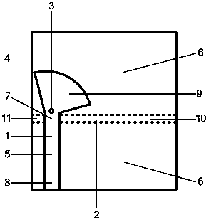
[0014] The technical scheme adopted in the present invention is: the transition between the microstrip line with the stop band and the slot line is composed of the microstrip line, the slot line and the metal grounding via hole, all of which are on the same circuit substrate; the conductor of the microstrip line The strip and the metal ground plane are respectively on both sides of the circuit substrate, and the metal ground plane of the microstrip line is etched to form a three-dimensional intersecting slot line with the conduction band of the microstrip line; one end of the microstrip line is the microstrip line- The first input and output port of the transition of the slot line, the other end is the end of the microstrip line, and the conduction band at the end of the microstrip line is a wide shape, which can be fan-shaped, rectangular, square or circular, etc. The i...


PUM


Abstract

The invention discloses a microstrip line-slot line transition structure with a stop band. The transition consists of a microstrip line (1), a slot line (2) and a metal grounding through hole (3) which are on the same circuit substrate (4); the slot line (2) in spatial vertical crossing (7) with a microstrip line conduction band (5) is etched on the metal grounding plane (6) of the microstrip line (1); one end of the microstrip line (1) is a first input / output port (8) of the microstrip line-slot line transition; the other end is the tail end (9) of the microstrip line; the conduction band of the tail end (9) of the microstrip line is in a broad shape; one end of the slot line (2) is a second input / output port (10) of the microstrip line-slot line transition; the other end of the slot line (2) is an open circuit end (11); and the tail end (9) of the microstrip line is provided with the metal grounding through hole (3) which passes through the circuit substrate (4). The transition can form the stop band in a work pass band and is used for inhibiting the interference with other systems which work in the stop band.

Description

technical field [0001] The invention relates to a microwave passive device, in particular to a microstrip line-slot line transition with a stop band in the working frequency band. Background technique [0002] Microstrip lines and slot lines are widely used in the microwave and millimeter wave frequency bands, and the transition between microstrip lines and slot lines has been particularly valued due to its simple structure and easy integration with printed structures. There are two types of commonly used microstrip line-slot line transitions: one is to reduce the reactance introduced by the transmission line to the input end of the microstrip line by using a suitable short-circuit end of the microstrip line and an open-circuit end of the slot line; The end of the line and the end of the slot line are designed as a resonant unit, so that the reactance of the two is cancelled. It is usually required to have a transitional operating frequency bandwidth and low in-band inserti...

Claims


Application Information

Patent Timeline
Patent Type & Authority Patents(China)
IPC IPC(8): H01P5/08
Inventor 殷晓星杨梅李顺礼赵洪新
Owner SOUTHEAST UNIV
Learn More