Lock-cylinder-free full-automatic puller

A fully automatic, lock cylinder technology, applied in the field of zippers, can solve the problems of cap travel limit, easy to produce adhesion, scratches and even grooves, etc., to achieve the effect of improving matching accuracy, preventing tooth bursting phenomenon, and low action requirements

Active Publication Date: 2011-07-27
JIANGSU CMZ ZIPPER SCI & TECH CO LTD
View PDF6 Cites 4 Cited by
  • Summary
  • Abstract
  • Description
  • Claims
  • Application Information

AI Technical Summary

Problems solved by technology

[0006] ① During the working process of the lock cylinder, the separation of the lock cylinder and the chain teeth is realized by lifting the pull piece manually. When the pull piece is in a free state, when the lock cylinder is not subjected to external force, it maintains a self-locking state. The lock cylinder is usually in a half-engaged state. If it is a metal zipper, it will cause the tip of the lock cylinder hook to be easily worn during the dragging contact with the teeth. This is because the braking force of the metal zipper decreases significantly after being used for a period of time. an important reason for
[0007] ②If the zipper has undergone surface treatment, such as the anti-corrosion coating coloring layer of the metal zipper, the vacuum coating layer of the nylon zipper, and the gold and silver coating of the resin zipper, the lock cylinder will have obvious scratches on the surface of the teeth of the zipper. Nylon and This phenomenon is especially serious for resin zippers, while metal zippers will have anti-corrosion coatings, damage and peeling of the coloring layer, which will seriously affect the aesthetics and service life of the zippers
[0008] ③If the material of the zipper is nylon wire or polyoxymethylene resin, after the zipper is used for a period of time, obvious scratches or even grooves will appear on the surface of the teeth that the lock cylinder contacts, resulting in a significant decrease or even loss of the braking force of the zipper. There will also be the problem that the zipper cannot be closed and the zipper is scrapped
[0009] ④During the actual use of zippers, in the self-locking state, such as winter clothes and bags, they often encounter large lateral tension. The lock core of the traditional self-locking slider has limited comprehensive strength due to its structure and cross-sectional size constraints, and it is easier to Bending deformation occurs or the teeth are directly damaged, resulting in the loss of self-locking force of the zipper or the scrapping of the slider
[0010] ⑤During use, when the zipper in the braking state is to be separated, the lock cylinder acts on the zipper teeth and is often at the dead point. At this time, it is necessary to overcome the resistance exerted by the shrapnel on the lock cylinder and the friction between the lock cylinder and the teeth. The zipper in this state needs a lot of manpower when starting, and it is not very smooth
[0011] 3. Cap strength is extremely weak
In recent years, in order to solve this problem, a four-point slider has been developed, that is, four riveting points are punched on the cap to fix it, which increases the cost, the slider assembly machine is more complicated, and the problem of falling off has been improved. In the washing environment, the problem of the cap falling off cannot be completely solved under the random impact and prying of the lever type of the pull tab
[0012] 4. The structure of the traditional slider determines the pull piece torque and low bonding strength
[0013] The torque and bonding strength of the pull piece are clearly stipulated in QB / T2171-2173. Due to the size limitation of the lock cylinder hole and the travel limit of the cap of the traditional slider, the beam diameter of the pull piece cannot be made to a larger size.
If the crossbeam exceeds the allowable diameter, the hook of the lock cylinder will be lifted and cannot act on the best stress-bearing part of the slider. If the cap and the slider body are enlarged, the cost will be a big test, and it will also affect the pull. The overall recognized appearance of the head
[0014] 5. The precise structure of the traditional slider determines that the zipper is extremely prone to sticking after painting
The common phenomenon is that the lock cylinder is not flexible, or it cannot be dropped after being lifted, or the coating cannot penetrate in, the surface of the lock cylinder is unprotected, and oxidation and corrosion occur during use and washing.
[0015] 6. The position of the lock cylinder of the traditional slider has limitations on the shape of the zipper teeth
Otherwise it will affect the normal insertion and positioning of the zipper latch
For example, if the slider is divided into the left side and the right side, the increase of different designs and varieties of all models will lead to the increase of one-stop production equipment, and the assembly in the workshop is easy to make mistakes, which increases the management cost and reduces the qualified rate of the products.

Method used


Image

  • Lock-cylinder-free full-automatic puller
  • Lock-cylinder-free full-automatic puller
  • Lock-cylinder-free full-automatic puller

Examples


Embodiment 1

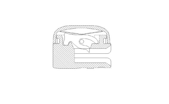
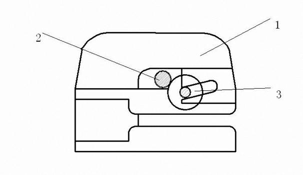
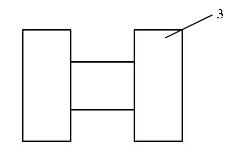
[0050] Embodiment 1, a lock cylinder-free automatic slider, the top of the main body 1 has a curved beam 6, the curved beam 6 and the main body 1 are a conjoined structure formed by one-time die-casting, the brake wheel 3 is installed under the curved beam 6, and the The central shaft is composed of rollers at both ends. The front end of the curved beam 6 is provided with a guide rail chute, and the central shaft of the brake wheel is placed in the guide rail chute. inside the hole. The body 1 and the curved beam 6 are integrally die-cast. The curved beam is opened during die-casting. When assembling, first put the pull piece 2 between the curved beam 6 and the body, and then put the central axis of the brake wheel 3 into the curved beam. In the chute of the guide rail on the beam, an assembly punching machine is used to punch down the plastic deformation of the curved beam to a specific size. At this time, the brake wheel 3 and the pull piece 2 are completely embedded in the ...

Embodiment 2

[0052] Embodiment 2, with reference to Embodiment 1, an elastic element 4 is added in the guide rail chute. This elastic element 4 can be a spring or a shrapnel or a spring needle to give the brake wheel a downward reset force for shortening the braking distance or Improve self-locking sensitivity.


PUM


Abstract

The invention provides a lock-cylinder-free full-automatic puller, relating to the technical field of zippers. The puller comprises a main body and a zipper puller, a camber beam is arranged at the top of the main body, the camber beam and the main body are of a conjoined structure formed by one-step die casting, a braking wheel composed of a central shaft and idler wheels at the two ends of the central shaft is arranged below the camber beam, the front end of the camber beam is provided with a guide rail chute, the guide rail chute is internally provided with the central shaft of the braking wheel, and the zipper puller is arranged in a hole formed by the camber beam, the braking wheel and the main body. The automatic puller provided by the invention has the advantages of high performance, high strength, relatively simple structure, relatively lower manufacturing cost, fewer quality control points and brand-new structure.

Description

technical field [0001] The invention relates to the technical field of zippers, in particular to a lock-free automatic slider for metal / nylon / resin zippers, which utilizes the friction principle of the centrifugal characteristics of wheel brakes to produce a braking effect. Background technique [0002] At present, the self-locking sliders used in the international and domestic zipper industry, the common structure see the attached figure 1 : The hollow cap is riveted on the zipper body. There is a horse hook and a spring piece built into the space of the cap. The spring piece is pressed on the top of the horse hook. The pull piece is in the groove of the horse hook. The lock cylinder hole through which the horse hook passes. The braking method adopted is to use the cooperation between the metal shrapnel and the lock cylinder, so that the needle tip falls into different positions of the teeth, hooks the teeth during the jump, realizes the braking of the slider on the zipper...

Claims


Application Information

Patent Timeline
IPC IPC(8): A44B19/30
Inventor 何福峰
Owner JIANGSU CMZ ZIPPER SCI & TECH CO LTD
Why Eureka
Try Eureka