Clathrates for gas storage
A gas hydrate, gas bag technology, applied in gas/liquid distribution and storage, gas fuel, fixed capacity gas storage tanks, etc., which can solve the limitations of kinetic and practical considerations, poor feasibility of clathrates, gas storage applications No cost-efficiency issues
- Summary
- Abstract
- Description
- Claims
- Application Information
AI Technical Summary
Problems solved by technology
Method used
Image
Examples
example 1
[0068] Example 1 - Synthesis of dry water
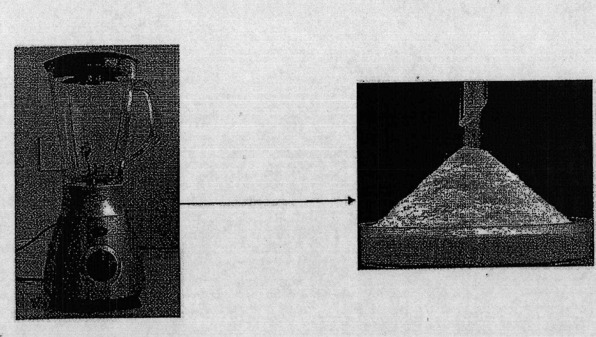
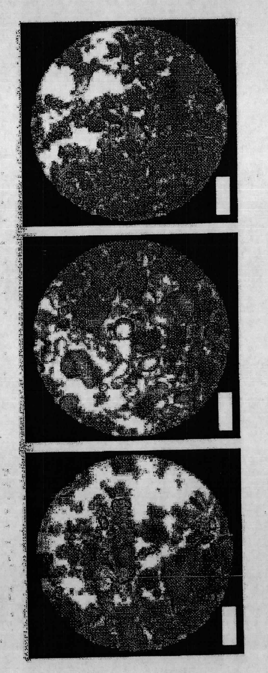
[0069] Full details of the dry water preparation procedure can be found elsewhere (Binks, B.P., Murakami, R. Nat. Mater. 2006, 5, 865-869). A sample of hydrophobic silica nanoparticles (H18) was provided by Wacker-Chemie. To prepare dry water powder, deionized water (95ml) was poured into a blender (Breville, Glass Jug Blender (Breville, Glass Jug Blender), BL18, 1.5 liters, with lid) and H18 (5g) was added to the water . Mixing was performed for 90 s at three different speeds (speed 1: average 16,450 rpm; speed 2: average 17,500 rpm; speed 3: average 19,000 rpm). The material produced was like a free-flowing "dry" white powder that could be poured from one container into another (see figure 2 ). The morphology of dry water was observed with an Olympus CX41RF microscope. Photographs were taken with a C-5060 digital camera (Olympus).
[0070] figure 1 A schematic is shown of a dry water droplet coated with small hydrophobic ...
example 2
[0071] Example 2 - Apparatus for gas hydrate formation
[0072] In order to carry out the gas absorption kinetics experiment, 20.0g of dry water (or made of glass beads (19.5cm 3 ) or unmixed water and silica (19.5cm 3 +0.5cm 3 ) in any composition of the control sample) loaded into the 68.0cm 3 High-pressure stainless steel reactor (New Ways of Analytics, Lorrach, Germany). The temperature of the coolant in the circulating water bath was controlled by a programmable thermodynamic circulator (HAAKE Phoenix II P2, Thermo Electron Corporation). The temperature of the composition in the high pressure reactor was measured with a type K thermocouple (Cole-Parmer, -250-400°C). Gas pressure was monitored with a high precision pressure transmitter (Cole Palmer, 0-3000 psia). Both thermocouples and transmitters were connected to a digital universal input panel meter (Cole Palmer) that communicated with the computer. Before the experiment, the reactor was slowly flushed three ti...
example 3
[0073] Example 3 (comparative) - control experiment
[0074] Figure 5 Control experiments are shown: in CH 4 P-T diagram of cooling and heating under pressure (temperature ramp: 2.0K / h): (a) and (b) 19.5cm 3 Glass beads; (c) and (d) unstirred mixture of water (19 g) and hydrophobic silica nanoparticles H18 (1 g). For the glass bead control experiments, the system approximated ideal gas behavior and no leaks were detected. Although a small pressure inflection change (<0.1 MPa) was observed, the behavior was similar to the unmixed water / silica control. This is most likely due to the very small extent of MGH formation at the gas-liquid interface.
PUM
| Property | Measurement | Unit |
|---|---|---|
| diameter | aaaaa | aaaaa |
| size | aaaaa | aaaaa |
| diameter | aaaaa | aaaaa |
Abstract
Description
Claims
Application Information
 - R&D
- Intellectual Property
- Life Sciences
- Materials
- Tech Scout
- Unparalleled Data Quality
- Higher Quality Content
- 60% Fewer Hallucinations
Browse by: Latest US Patents, China's latest patents, Technical Efficacy Thesaurus, Application Domain, Technology Topic, Popular Technical Reports.
© 2025 PatSnap. All rights reserved.Legal|Privacy policy|Modern Slavery Act Transparency Statement|Sitemap|About US| Contact US: help@patsnap.com


