
Multi-stage depressed collector with lining grid and manufacturing method and application thereof

A collector and grid technology, which is applied in the collectors of transit-time electron tubes, the manufacture of non-light-emitting electrodes, and electron tubes with velocity/density modulation electron flow, etc., to achieve the effect of improving efficiency and suppressing emission

Inactive Publication Date: 2011-07-06
INST OF ELECTRONICS CHINESE ACAD OF SCI
View PDF0 Cites 8 Cited by
  • Summary
  • Abstract
  • Description
  • Claims
  • Application Information

AI Technical Summary

Problems solved by technology

However, pyrolytic graphite or high-density isotropic graphite used in multi-stage pressure-reducing collectors requires special method equipment and method flow, and there has not been any report yet

Method used


Image

  • Multi-stage depressed collector with lining grid and manufacturing method and application thereof
  • Multi-stage depressed collector with lining grid and manufacturing method and application thereof
  • Multi-stage depressed collector with lining grid and manufacturing method and application thereof

Examples


Embodiment Construction

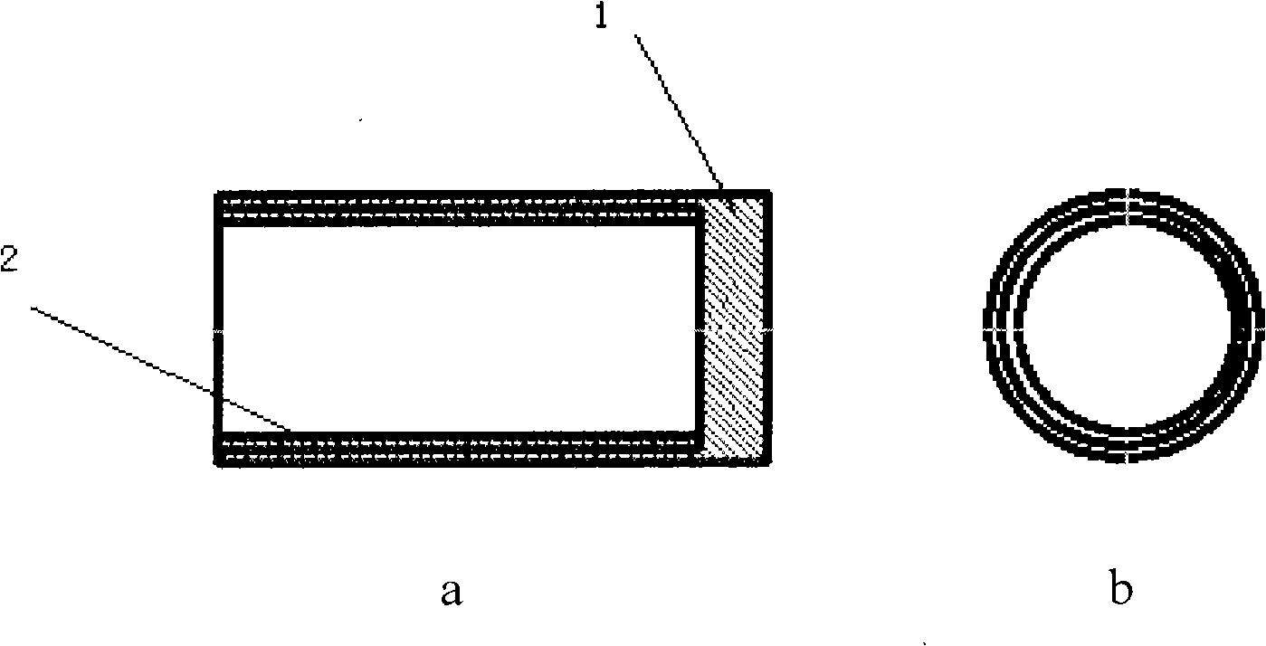
[0033] The invention proposes an electrode structure in which a metal mesh is lined inside the metal electrode. Because for the same material, the secondary electron emission coefficient of the rough surface is smaller than that of the smooth surface. In the present invention, a layer of flat metal grid is attached to the inner surface of the electrode of the smooth multi-stage step-down collector. roughness, which can effectively reduce the secondary electron emission coefficient.

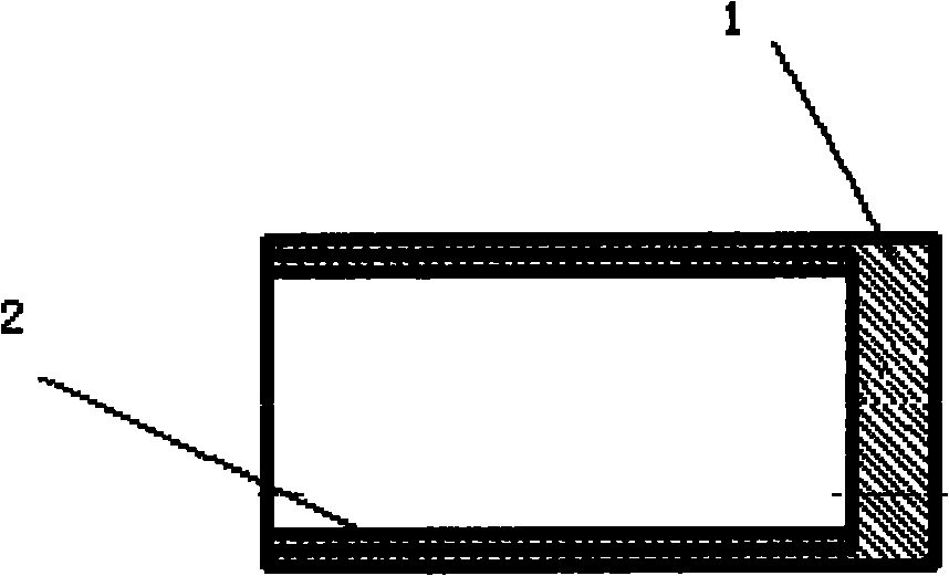
[0034] The main technical solution of the invention is to line the inner surface of the multi-stage pressure-reducing collector with a metal grid to suppress the emission of secondary electrons. Such as figure 1 As shown, the inner surface of the known multi-stage decompression collector 1 is lined with a metal grid 2 .

[0035] The specific method of the present invention lining metal grid on the inner surface of the multi-stage step-down collector is:

[0036] Purchase nickel, molybdenum, tu...


PUM

PropertyMeasurementUnit
Thicknessaaaaaaaaaa
Mesh densityaaaaaaaaaa

Abstract

The invention relates to a multi-stage depressed collector with a lining grid, which is designed based on the principle that a metal grid is embedded in the inner surface of the multi-stage depressed collector in order to suppress the emission of secondary electrons, wherein the metal grid is made of nickel, molybdenum, tungsten, oxygen-free copper or stainless steel and is 0.1-0.3 mm in thickness, and the mesh density ranges from 50 to 200 meshes. The manufacturing method of the collector comprises the step of punching or curling a plane metal grid. In the invention, the emission of secondary electrons is suppressed and the efficiency of the multi-stage depressed collector is improved by using a method of embedding the metal grid in the inner surface of the electrode of the multi-stage depressed collector.

Description

technical field [0001] The invention relates to a multi-stage pressure-reducing collector with an inner liner grid. [0002] The present invention also relates to a preparation method of the above-mentioned multi-stage pressure-reducing collector. [0003] The present invention also relates to the application of the above-mentioned multi-stage step-down collector. Background technique [0004] The traveling wave tube is one of the important members of the family of microwave electric vacuum devices. It is a device that amplifies the electromagnetic wave by interacting with the electron beam in the interaction area of ​​the traveling wave tube. Traveling wave tube generally consists of five parts: electron gun, magnetic focusing system, slow wave structure, energy transmission device, single-stage or multi-stage step-down collector. Among them, the multi-stage step-down collector is the key component of various traveling wave tubes and some klystrons. Its function is to rec...

Claims


Application Information

Patent Timeline
IPC IPC(8): H01J23/027H01J9/14H01J25/34H01J25/10
Inventor 王自成董芳
Owner INST OF ELECTRONICS CHINESE ACAD OF SCI
Learn More