Low-temperature sintering method for high-performance Fe-based powder metallurgy parts
An iron-based powder metallurgy and low-temperature sintering technology, applied in the field of powder metallurgy, can solve the problems of high requirements and losses of sintering furnaces, increase production costs, and few research reports, and achieve the advantages of increasing raw material costs, prolonging service life, and broadening application fields. Effect
- Summary
- Abstract
- Description
- Claims
- Application Information
AI Technical Summary
Problems solved by technology
Method used
Image
Examples
Embodiment 1
[0028] Mix 0.5~0.8wt.% mold release agent and the rest is common iron powder evenly and press to shape, then sinter at 1120oC for 3h and then cool with the furnace.
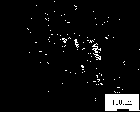
[0029] figure 1 It is the surface morphology of iron-based powder metallurgy parts without adding nano-copper powder after sintering at 1120oC, and the black area is the surface porosity. It can be seen that the surface sintered at 1120oC is relatively dense, and iron-based powders can be effectively bonded at this temperature At the same time, it can also be seen that there are certain irregular pores on the surface, in which the grain diameter is between 30 and 80 μm, and a small amount of grain diameter reaches 100 μm.
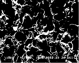
[0030] figure 2 SEM fracture morphology of iron-based powder metallurgy parts without nano-copper powder added after sintering at 1120oC, from which it can be observed that there are a certain number of dimples on the fracture surface, which has a certain degree of plasticity, and it can be ...
Embodiment 2
[0035] Mix 0.5~0.8wt.% mold release agent and the rest is common iron powder evenly and press to shape, then sinter at 880oC for 3h and then cool with the furnace.
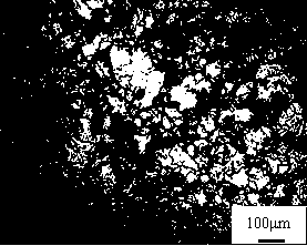
[0036] image 3 It is the surface morphology of iron-based powder metallurgy parts without adding nano-copper powder after sintering at 880oC, and figure 1 In comparison, it can be seen that there are a large number of pores on the surface of the part, and most of the pores exist at the grain boundary, the grain size is 30 μm to 150 μm, and the number of large-sized grains increases.
[0037] Figure 4 The SEM fracture morphology of the green body of iron-based powder metallurgy parts without adding nano-copper powder, and figure 2 In comparison, a large number of dissociated surfaces and a certain number of cracks can be seen, indicating that the interior of the unsintered part is only the mechanical interlocking between powders, without the bonding between atoms, the corresponding performance requirements can...
Embodiment 3
[0043] 0.5~0.8wt.% mold release agent, 0.1~0.5wt.% nano-copper powder, and the rest are ordinary iron powder mixed evenly and pressed into shape, then sintered at 880oC for 3 hours and then cooled with the furnace.
[0044] Figure 6 In order to add 0.3wt.% nano-copper powder to the surface morphology of iron-based powder metallurgy parts after sintering at 880oC, and figure 1 The difference is: firstly, the pores on the surface of the parts added with nano-copper powder are dispersed and evenly distributed in the structure (grain boundary and inside the grains), without forming large polygonal pores; secondly, there are more near-spherical isolated pores; , the grain size is also small, mostly in the range of 30~50μm, and its corresponding properties are listed in Table 3.
[0045] Figure 7 SEM fracture morphology of iron-based powder metallurgy parts added with 0.3wt.% nano-copper powder after sintering at 880oC, a large number of dimples can be seen, indicating that the ...
PUM
| Property | Measurement | Unit |
|---|---|---|
| particle diameter | aaaaa | aaaaa |
| particle diameter | aaaaa | aaaaa |
| diameter | aaaaa | aaaaa |
Abstract
Description
Claims
Application Information
 - R&D
- Intellectual Property
- Life Sciences
- Materials
- Tech Scout
- Unparalleled Data Quality
- Higher Quality Content
- 60% Fewer Hallucinations
Browse by: Latest US Patents, China's latest patents, Technical Efficacy Thesaurus, Application Domain, Technology Topic, Popular Technical Reports.
© 2025 PatSnap. All rights reserved.Legal|Privacy policy|Modern Slavery Act Transparency Statement|Sitemap|About US| Contact US: help@patsnap.com


