Spray for fluent materials
a fluent material and spray technology, applied in the field of spraying for fluent materials, can solve the problems of poor mixing, interfering with the proper dispensing of materials into the supply line, excessive distension of tissue surrounding the operative site, etc., to prevent cross-talk, improve the effect of mixing, and easy measuremen
- Summary
- Abstract
- Description
- Claims
- Application Information
AI Technical Summary
Benefits of technology
Problems solved by technology
Method used
Image
Examples
example 1
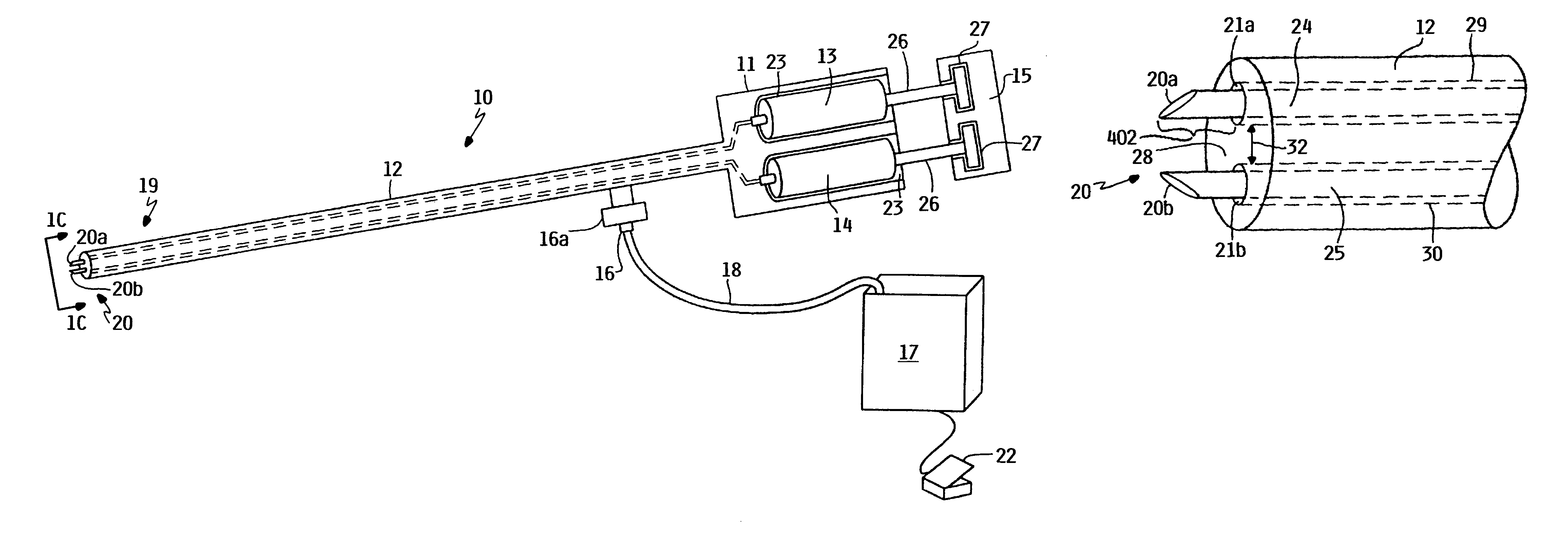
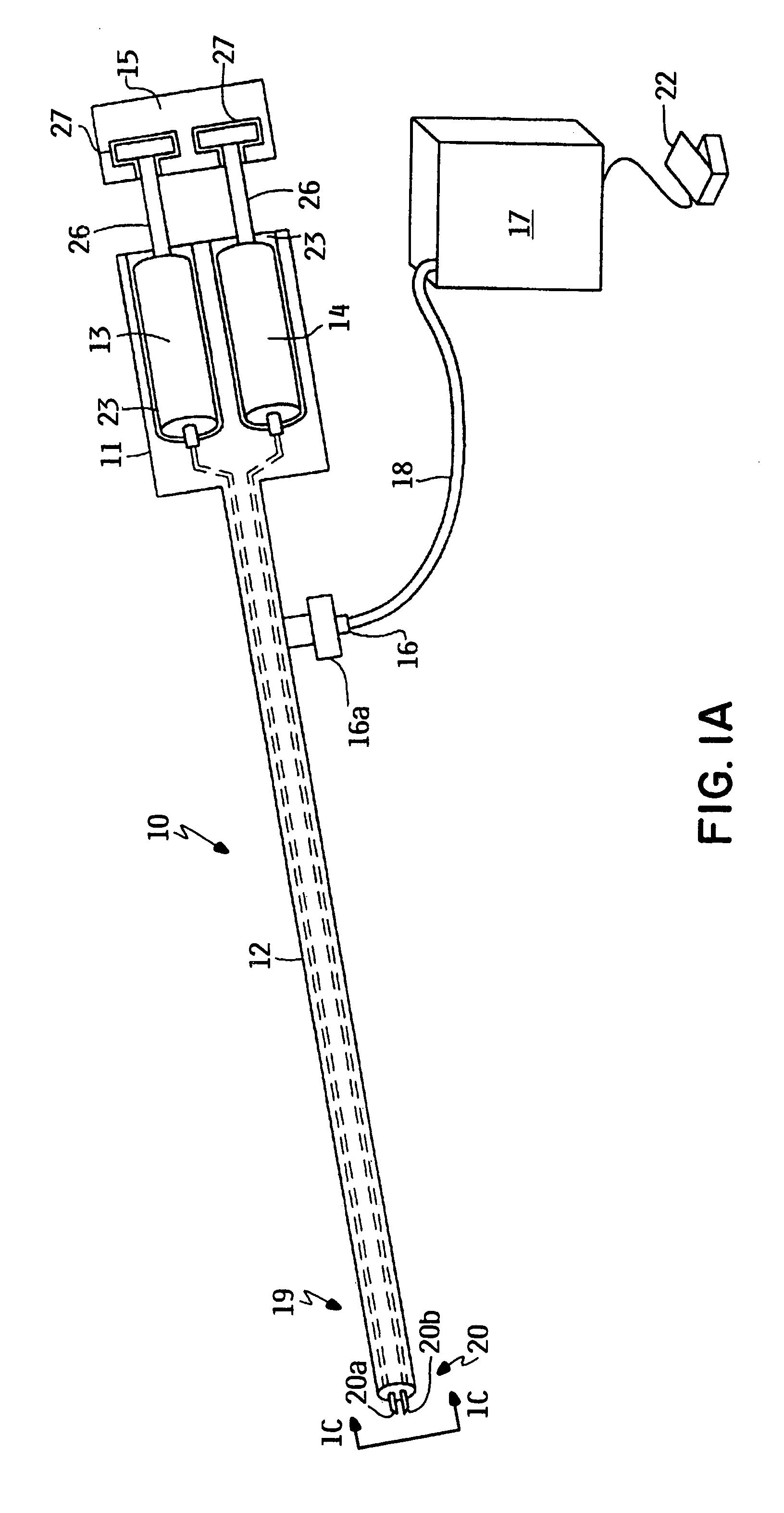
[0104]Sprayer 10 of FIG. 1 is used in conjunction with aqueous solutions of crosslinkable monomers. Solution 1, consisting of a 10% solution of a polyethylene glycol diacrylate (M.W. 3,000 Da, purchased from Shearwater Polymers, Huntsville, Ala.) dissolved in normal saline (pH 5-6) and containing 500 ppm of hydrogen peroxide is drawn up in syringe 13, preferably a 5 cc syringe. Solution 2, consisting of a 10% solution of a polyethylene glycol diacrylate dissolved in normal saline (pH 5-6) and containing 5000 ppm of ferrous sulfate peroxide, is drawn up in syringe 14, also a 5 cc syringe. Syringes 13 and 14 are individually loaded in compartments 23, and are coupled to conduits 24 and 25 and actuator 15.
[0105]Airflow from a regulated source of compressed air (an air compressor such as those commercially available for airbrushes) is connected to the sprayer 10 using a piece of tubing. When actuator 15 is depressed, a steady spray of the two liquid components will be observed. When thi...
example 2
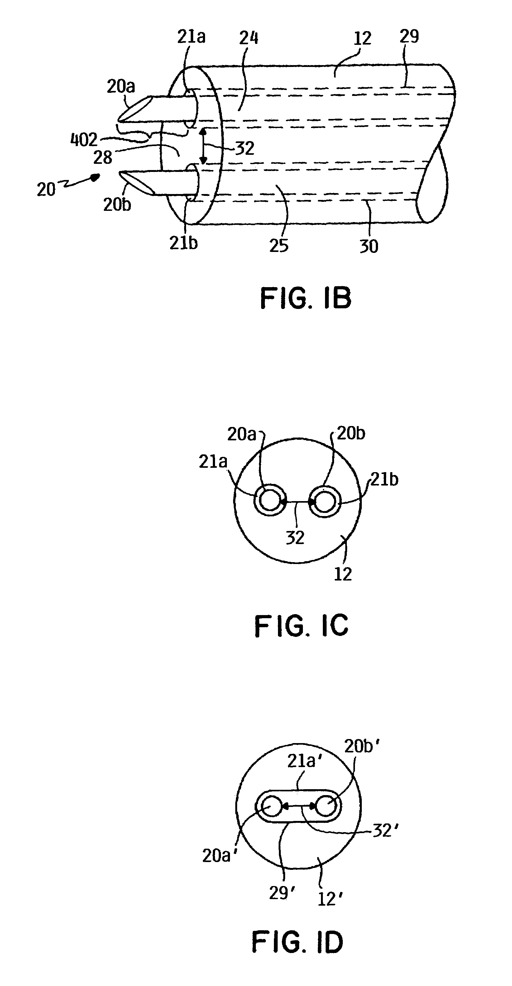
[0106]A sprayer as in sprayer 10 of FIG. 1 was mounted in a rigid system in a horizontal position for a horizontal spray test. The sprayer was essentially identical to sprayer 10, except that the gas flow outlets and conduits were arranged as depicted in FIG. 6A, 6B. The angle 511, and was about 90 degrees, sheath 512 was made of plastic, and encompassed conduits 504, 506, to define gas outlet 514. Gap 516 was about 0.7 mm.
[0107]The tip of each sprayer was a distance of 2 cm from the target location, a vertical mylar sheet. In each of the syringes 13 and 14 was placed 1 mL of DuraSeal® sealant. Plungers 26 were depressed to dispense 0.2 mL (0.1 mL per syringe). The sprayer 10 was left to stand for 30 seconds. Then an additional 0.2 mL (0.1 mL per syringe) increment was delivered. This was repeated until the entire polymer was delivered in 0.2 mL increments with 30 seconds of standing between each application. The same procedure was followed for sprayer 10 that contained a straight o...
example 3
[0110]Sprayers were tested to determine the air flow required to achieve both good mixing and good material formation from the compositions. Sprayers as in Example 2 were mounted vertically in a rigid fixture suspended 4 cm form a target of mylar. The sprayers were connected to an air source with a regulator, and the mass flow of the air was adjusted to range between 0.2 to 1.0 liters / minute. A total volume of 0.4 ml of the material formed from the precursors was deposited on the target at each flow rate. The pattern of material formed on the target was observed. At 1.0 l / min, the material was deposited in a volcano-shape, i.e., a circle with relatively more material deposited around the edges of the circle. At rates below 0.4 l / minute, the applicator tended to clog. The 0.6 ml / minute rate made a pattern that was relatively more consistent in thickness and quality compared to 0.8 ml / minute rate, which showed a more significant volcano effect.
PUM
 Abstract
Description
Claims
Application Information
 - R&D
- Intellectual Property
- Life Sciences
- Materials
- Tech Scout
- Unparalleled Data Quality
- Higher Quality Content
- 60% Fewer Hallucinations
Browse by: Latest US Patents, China's latest patents, Technical Efficacy Thesaurus, Application Domain, Technology Topic, Popular Technical Reports.
© 2025 PatSnap. All rights reserved.Legal|Privacy policy|Modern Slavery Act Transparency Statement|Sitemap|About US| Contact US: help@patsnap.com


