
Bionic aircraft

A bionic aircraft and shock absorber technology, applied in the field of bionic aircraft, can solve the problems of clumsy flying attitude, poor attitude control, complicated structure, etc., and achieve the effects of rapid and agile change, reasonable aerodynamic pattern, and favorable take-off.

Inactive Publication Date: 2011-06-29
姚金玉
View PDF5 Cites 37 Cited by
  • Summary
  • Abstract
  • Description
  • Claims
  • Application Information

AI Technical Summary

Problems solved by technology

[0004] So far, people have designed a variety of flapping-wing aircraft, but those that can take off into the air are only some better-designed models, and the time left in the air is also shorter, and can only fly for a few minutes, while the flapping-wing aircraft that can carry people So far, it has not appeared in the blue sky. The reason is: some manned flapping-wing aircraft, the design of the transmission system is too simple, such as using the arm to drive the flapping wing, obviously the strength of the human arm is not enough. The transmission system of the current model uses a crankshaft-connecting rod mechanism, so that the amplitude and frequency of the flapping of the wings are constant, and the lift generated is small. Rods, hydraulic devices, solenoid valves and various types of gears make the structure too complicated, increase the number of failure points, and also greatly increase the weight of the aircraft
[0005] Some flapping-wing aircraft use the driver to move the body to adjust the center of gravity of the aircraft, which is awkward to change the flight attitude
In addition, the main wings and tail wings of most flapping-wing aircraft cannot be extended or retracted, and the attitude during flight is not easy to control

Method used


Image

  • Bionic aircraft
  • Bionic aircraft
  • Bionic aircraft

Examples


Embodiment 1

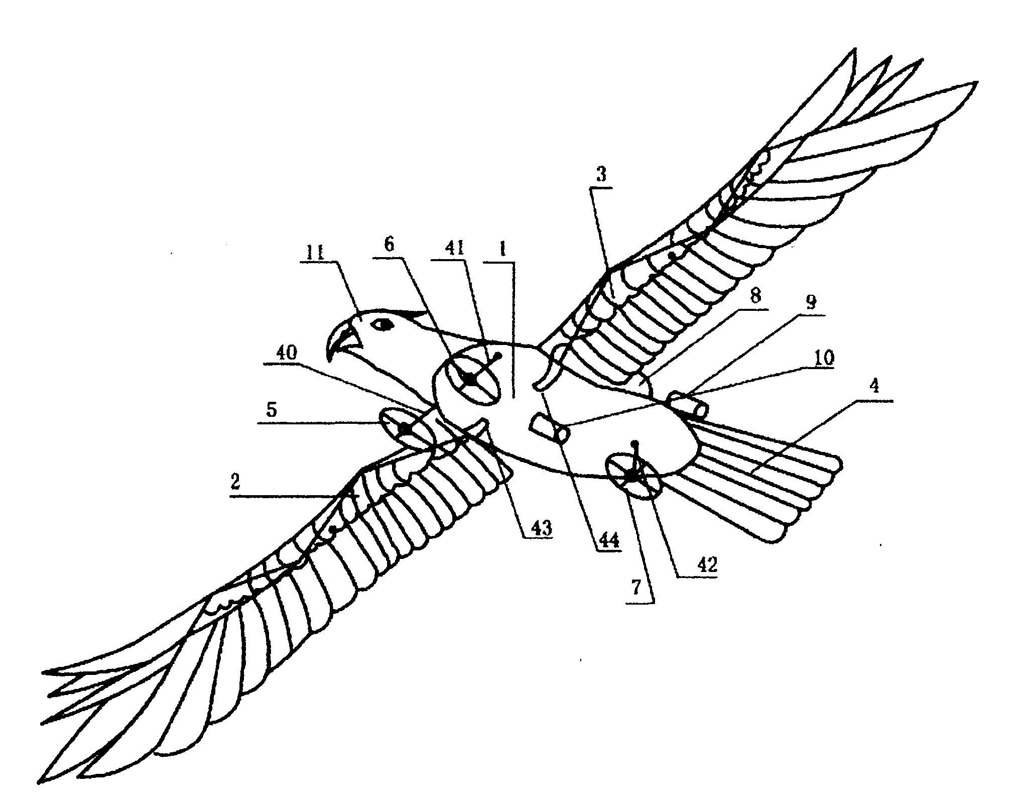
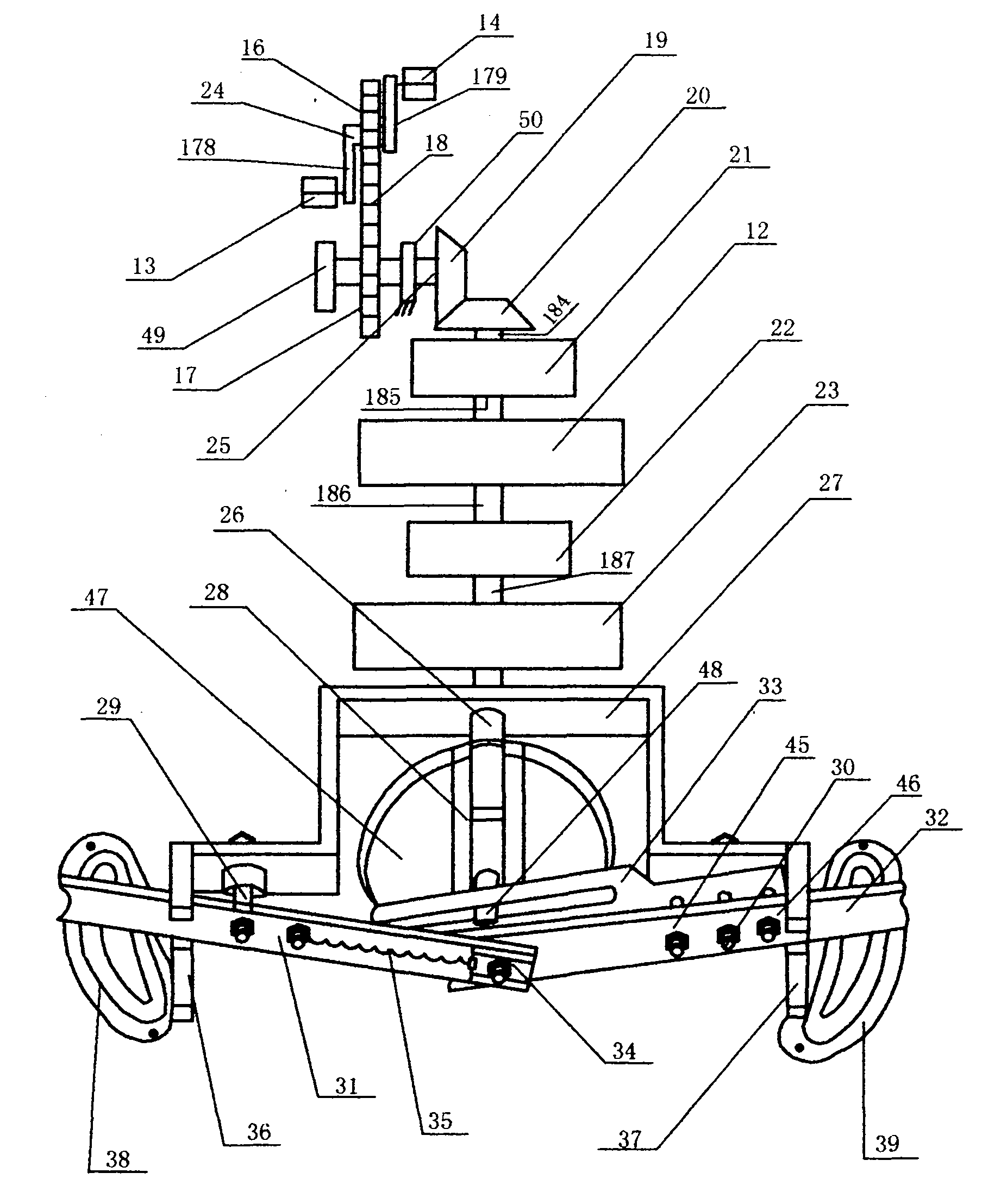
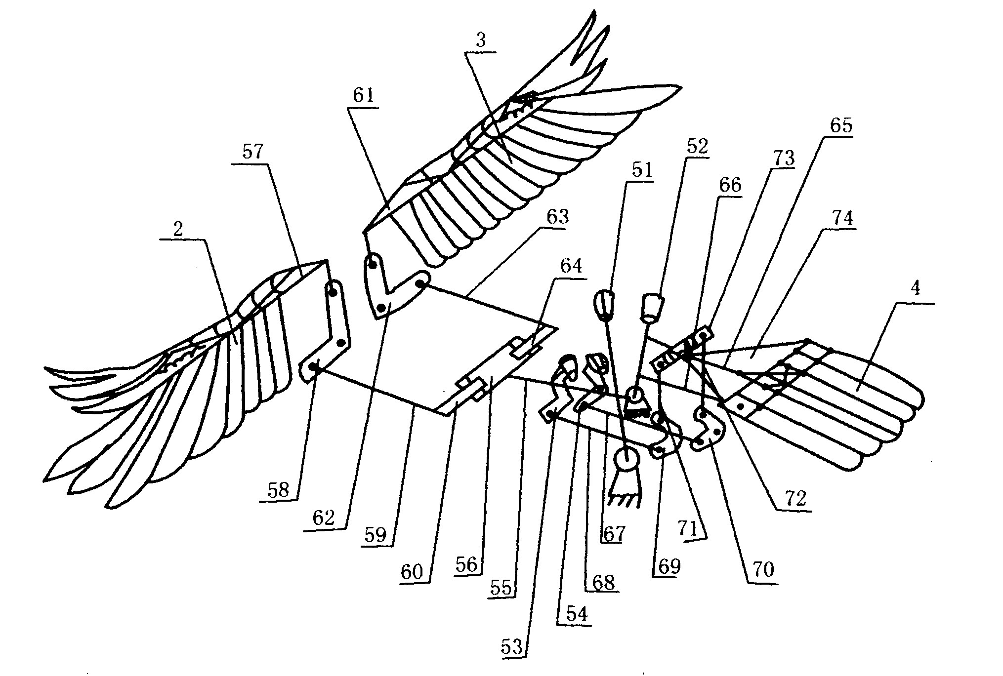
[0039] Embodiment 1: the structure of the present invention is as figure 1 Shown, on the top of the body (1), the tandem parallelogram retractable main wings (2, 3) are assembled bilaterally symmetrically, and the bidirectional parallelogram parallelogram retractable flat empennage (4) is assembled at the rear of the body (1). The underside of the body (1) is assembled into landing gear shock absorbers (40, 41, 42) arranged at three points, and landing gear wheels (5, 6, 7) are assembled on one end of the shock absorbers (40, 41, 42) respectively. , the cockpit (8), the safety umbrella storehouse (9), are assembled on the top of the body (1), the cockpit (8) is before the safety umbrella storehouse (9), and the solid rocket flying aid (10) is assembled on the body (1) ), its axis forms an included angle of 10 to 15 degrees below the central axis of the body (1), the spout faces to the rear and downward, the machine head (11) is assembled in front of the body (1), and the trans...

Embodiment 2

[0063] Embodiment 2: Fig. 7, Figure 8 , Figure 9 Shown are three views of this embodiment, Figure 8 is a front view, and Figure 7 is a top view, Figure 9 It is a left side view, and the present embodiment is to increase a fixed wing of assembling above the center of gravity of the bionic aircraft described in embodiment 1; Delta wing (or rectangular wing), flat tail (4) is refitted into vertical tail (182), horizontal tail (178,179) combined empennage, rudder (183), elevator (180,181).

[0064]Fix assembly with bar member (190,191,192,193) between the triangle fixed wing (189) and the body (1), and one end of dragline (196,197,200,201) is fixedly installed on support bar ( 194), the other end is respectively fixed on the top of the three corners of the triangular fixed wing (189) and the middle position of a side, and one end of the dragline (192, 193, 199, 202) is respectively fixed on the triangular fixed wing (189). Below the middle position of fixed wing (189) belo...

Embodiment 3

[0067] Embodiment 3, Figure 10 , Figure 11 , Figure 12 Shown are three views of this embodiment. Figure 11 is the main view, Figure 10 is a top view, Figure 12 is the left view. In this embodiment, the fixed delta wing above the body (1) of Embodiment 2 is refitted into two streamlined airbags arranged symmetrically in the form of two osprey boats with equal volume and weight. The airbag is supported by a ring skeleton made of aluminum-magnesium alloy or carbon fiber of different sizes. There is a longitudinal opening under each airbag, and a group of gas nozzles are installed at the opening of the lower end of each airbag to fill the airbag with hot gas; or use a sealed The airbag is filled with helium inwardly to provide part of the lift to the aircraft, and the other part of the lift is provided by the main wings (2, 3). When the aircraft is not loaded, it is lighter than the air, and when it is loaded, it is slightly heavier than the air. The thrust of the aircr...


PUM


Abstract

The invention discloses a bionic aircraft. Series parallelogram telescopic main wings (2, 3) are symmetrically assembled on the left and the right above a body (1), bidirectional parallel parallelogram telescopic flat tail wings (4) are assembled in back of the body (1), undercarriage shock absorbers (40, 41, 42) arranged in three points are assembled below the body (1), undercarriage wheels (5, 6, 7) are assembled at one end of each of the shock absorbers (40, 41, 42) respectively, a driving cabin (8) and a safety umbrella cabin (9) are assembled above the body (1), the driving cabin (8) is positioned in front of the safety umbrella cabin (9), a solid rocket jato (10) is assembled at the lower gravity center position of the body (1), and the central axis of the solid rocket jato (10) and the central axis of the body (1) form an included angle of 10 to 15 degrees downwards. A nozzle faces to the lower rear part, a nose (11) is assembled in front of the body (1), and a power transmission mechanism and an operating system are assembled in the body (1). Because of the adoption of a bionic technology, the aircraft can simulate various flying postures of birds; the amplitude and frequency modulation transmission mechanism is favorable for rising, landing and flying of the aircraft; by adopting human-machine hybrid power, the aircraft has no pollution; because of good folding property of main rings, the aircraft is convenient for transportation; and the aircraft can be used for sports, escape, downhill race, patrol and the like.

Description

1. Technical field [0001] The invention relates to a bionic aircraft in the aviation field. 2. Technical background [0002] Flying freely in the sky like a bird has been the pursuit of human beings since ancient times. According to legend, Lu Ban, the founder of my country's construction industry in ancient times, once made a wooden bird with a bamboo structure, which could fly in the sky for three consecutive days. Han Xin, a famous general in the Western Han Dynasty, once used a kite to carry out manned flights. Modern German engineer Lilienthal designed and manufactured a cordless kite, a glider, which has successfully carried out many manned flights. With the advancement of human science and technology, in 1903 AD, the Wright brothers of the United States installed an internal combustion engine on the glider and successfully carried out manned flight by means of propeller propulsion, thus creating a new era of human flight. [0003] In the past hundred years since the...

Claims


Application Information

Patent Timeline
IPC IPC(8): B64C33/02
Inventor 姚金玉
Owner 姚金玉
Learn More