
Fuel feeding method of direct liquid fuel cell system

A liquid fuel cell and feeding method technology, applied in fuel cells, fuel cell additives, circuits, etc., can solve the problems of increasing system energy consumption, fuel utilization rate and system energy density, less public patents, and reducing system energy Density and system reliability and other issues, to achieve the effect of reducing volatile loss, convenient and flexible manufacturing and use, and improving fuel utilization

Active Publication Date: 2011-06-22
DALIAN INST OF CHEM PHYSICS CHINESE ACAD OF SCI
View PDF2 Cites 7 Cited by
  • Summary
  • Abstract
  • Description
  • Claims
  • Application Information

AI Technical Summary

Problems solved by technology

The method of supplementing high-concentration fuel or pure fuel into the anode circulation system of the stack is usually realized by a liquid pump of moving parts, but the use of a liquid pump usually increases the energy consumption of the system, reduces the energy density and system reliability
[0004] At present, there are still few literatures and published patents on the influence of fuel feeding methods on the fuel utilization rate and system energy density of direct liquid fuel cell systems.

Method used


Image

  • Fuel feeding method of direct liquid fuel cell system
  • Fuel feeding method of direct liquid fuel cell system
  • Fuel feeding method of direct liquid fuel cell system

Examples


Embodiment

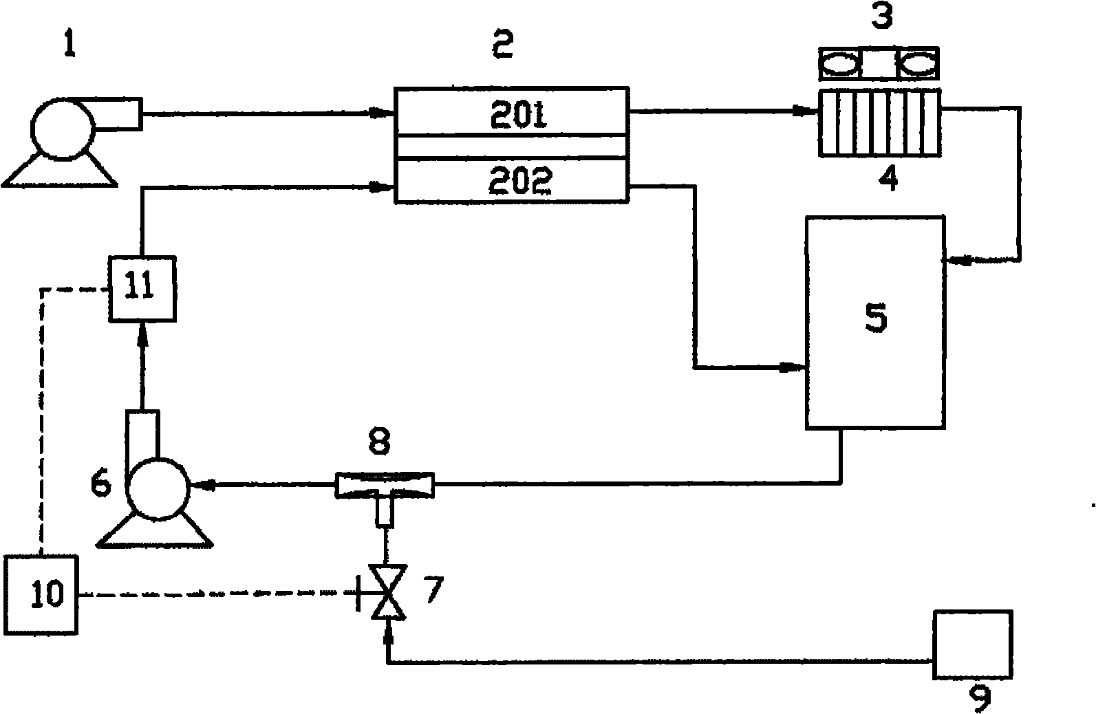
[0023] figure 1 It is a schematic flow chart of the method for feeding pure methanol to the DMFC system of the present invention. The DMFC system shown includes direct methanol fuel cell stack 2, air pump 1, fan 3, heat exchanger 4, gas-liquid separator 5, liquid pump 6, pure methanol tank 9, throttle valve 8, solenoid valve 7, control Device 10 and methanol concentration sensor 11.

[0024] During the working process of the above-mentioned DMFC system, its ambient temperature is room temperature (25°C), and its external output power is constant at 50W. During operation, the air pump 1 transports the outside air to the cathode 201 of the direct methanol fuel cell stack 2, and the outlet of the cathode 201 The gas-liquid mixture enters the gas-liquid separator 5 after being condensed by the heat exchanger 4. In order to improve the heat exchange efficiency of the system, a fan 3 is arranged above the heat exchanger 4; the gas-liquid mixture at the outlet of the anode 202 of th...


PUM


Abstract

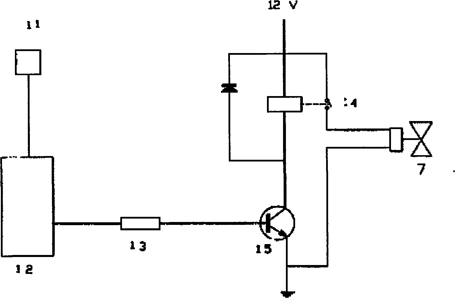
The invention relates to a fuel feeding method of a direct liquid fuel cell system. The direct liquid fuel cell system comprises a cell galvanic pile, a heat exchanger, a gas-liquid separator and a fuel tank. A gas-liquid mixture positioned on a cathode outlet of the cell galvanic pile passes through the heat exchanger and then enters the gas-liquid separator; a gas-liquid mixture positioned on an anode outlet of the cell galvanic pile directly enters the gas-liquid separator; a connecting pipeline of a material outlet of the gas-liquid separator and an anode inlet of the cell galvanic pile is sequentially provided with a throttling valve and a liquid pump; a branch circuit is arranged between the throttling valve and the liquid pump and connected with a fuel tank pipeline through an electromagnetic valve; fuel inside the fuel tank enters the anode of the cell galvanic pile through the connecting pipeline positioned between the material outlet of the gas-liquid separator and the anodeinlet of the cell galvanic pile, and the anode inlet is provided with a concentration sensor; and an output signal of the concentration sensor is processed by a controller and then electrically connected with the electromagnetic valve through the controller by using a conducting wire. due to the adoption of the fuel feeding method, the usage of moving parts of the direct liquid fuel cell system and the energy consumption of the direct liquid fuel cell system are reduced, the manufacture and usage of the throttling valve are convenient and flexible, the system integration is easier and the system stability is improved.

Description

technical field [0001] The invention relates to a fuel feeding method for a direct liquid fuel cell system. The method reduces the energy consumption of the system by reducing the use of moving parts in the system. At the same time, the manufacture and use of the throttle valve in the system is convenient and flexible, and it is easier for system integration and maintenance. Improvement of system reliability. On the other hand, the method reduces the fuel loss and improves the fuel utilization rate of the system by reducing the concentration of the fuel in the gas-liquid separator. Background technique [0002] Direct liquid fuel cell is an electrochemical reaction device that directly converts chemical energy in fuel (methanol, ethanol, ethylene glycol, propanol, formic acid, acetic acid) into electrical energy. Due to the high specific energy density of this type of fuel and the simple structure of the fuel cell system, this type of battery has broad application prospects...

Claims


Application Information

Patent Timeline
Patent Type & Authority Applications(China)
IPC IPC(8): H01M8/04H01M8/22H01M8/04082
CPCY02E60/50Y02P70/50
Inventor 孙公权陈利康孙海赵钢秦兵
Owner DALIAN INST OF CHEM PHYSICS CHINESE ACAD OF SCI
Learn More