
Efficient multifunctional energy system optimization set

An energy system and multi-functional technology, applied in the direction of machines/engines, mechanical equipment, mechanisms that generate mechanical power, etc., can solve problems such as high cost and maintenance, small application range, and low efficiency of air energy acquisition devices

Inactive Publication Date: 2011-06-22
于志伟
View PDF0 Cites 10 Cited by
  • Summary
  • Abstract
  • Description
  • Claims
  • Application Information

AI Technical Summary

Problems solved by technology

[0009] The medium and high temperature geothermal application of 65°C-550°C also has formation drilling depths of 3-10 kilometers, few high-temperature geothermal resources, high cost and maintenance difficulties, making practical application more difficult
[0012] Ordinary air energy harvesting devices are inefficient. For example, air energy heat pump air conditioners have a thermal efficiency ratio of only about 2.5-6.0 and are mainly used for cooling and heating. The scope of application is small. For example, it is difficult to use for power generation and the efficiency is too low. With the help of ordinary solar energy focusing, the cost is high, the engineering cost is high, and it is even more difficult to increase the power, etc.
[0013] In view of the existence of the above defects, it is difficult to further improve the economic and technical performance, and it is difficult to optimize the integration

Method used

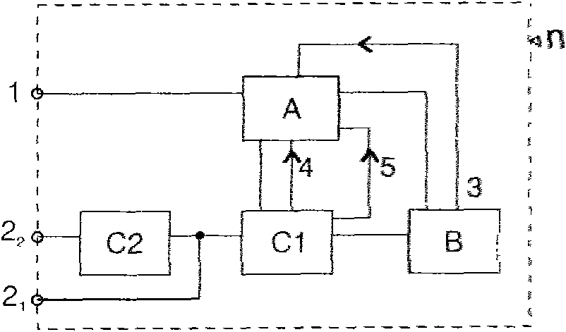
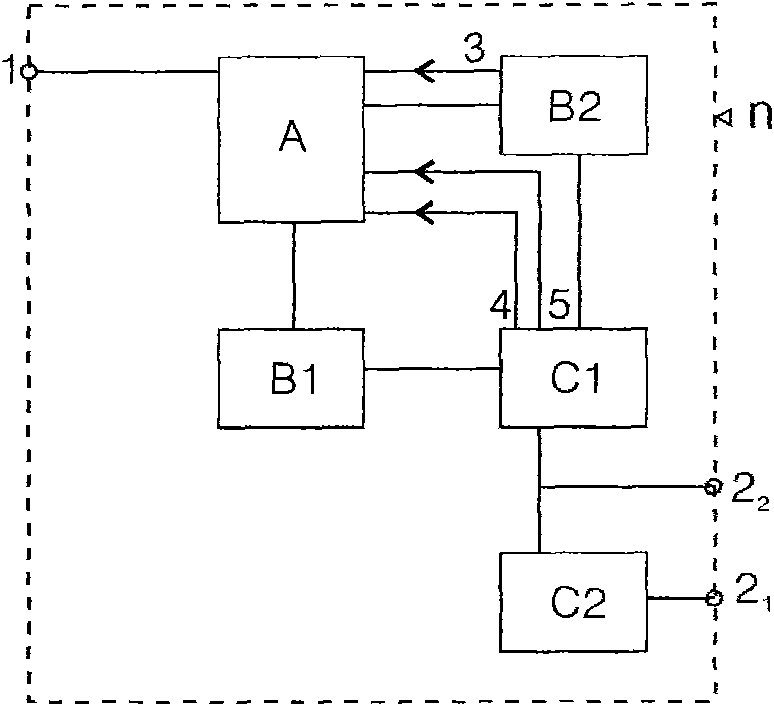

Image

  • Efficient multifunctional energy system optimization set
  • Efficient multifunctional energy system optimization set
  • Efficient multifunctional energy system optimization set

Examples


Embodiment 1

[0573] The present invention simultaneously applies the thermoelectric power generation system to generate electricity in a hydroelectric power station. Together with the hydroelectric power generation, the power of the entire thermoelectric power station can usually be 450%-750% of the original hydroelectric power station, combined with low temperature or high temperature air, up to 1389%! That is to expand to 13.89 times the amount of hydropower! % (Refer to P86 Case 11). In each system, it can also be combined with sunlight concentration to obtain amazing effects under the same water resource conditions, which has huge economic, commercial, environmental protection, emission reduction, and social benefits.

[0574] Comprehensively improve the design of the heat engine system, improve the heat exchanger, compressor, subcooling circuit, etc., make the system suitable for the low temperature R744 refrigerant used, and greatly improve the efficiency and environmental performance, ...

Embodiment 2

[0604] Example 2: Combination of water source combined with air source, solar concentrating array energy, solar thermal energy, shallow low-temperature geothermal source (or other heat sources or various heat sources with energy numbers N1-N26 of the present invention): the principle is two Or the energy difference between the two groups of energy is large, easy to obtain, and more economical and stable, increasing the energy stability of the entire system and the collection, improving complementary advantages, environmental protection, etc., if the temperature difference of the water source can be reduced in winter, choose air The energy of the source and / or shallow geothermal energy is reduced. For example, when the average temperature of the water source drops, or the temperature difference decreases, the temperature difference between it and the air source and geothermal increases, that is, the temperature difference of the water source itself decreases the power generation, ...

Embodiment 3

[0612] Water source combined energy and

[0613] The surplus energy of the water temperature difference and other surplus energy generate multiple power generation and production capacity (or generate power and energy):

[0614] The remaining energy of the water temperature difference is combined with air source, solar concentrating array energy, solar thermal energy, shallow low temperature geothermal source (or other heat sources or various heat sources with energy numbers N1-N26 of the present invention), or water sources are combined with the aforementioned energy sources, Or the air source and the shallow low-temperature geothermal source are combined with the water source at the same time, or any combination of the aforementioned multiple combinations (the following detailed combination arrangements) are combined again with the water source to generate electricity (or power, energy):

[0615] Air thermal energy (which can include solar thermal energy, solar concentrating energy...


PUM


Abstract

The invention relates to a cyclic regeneration environmentally-friendly energy system optimization set. A hydraulic power and temperature difference generating system is used for converting energy, optimizing the system and automatically controlling an output and input energy feedback distribution ring and a bus and has sharply increased power density, output power and efficiency and stability. The power of a power station is 450 to 750 percent of that of the original power station and can reach 1389 percent of that of the original power station to the maximum extent, so that the capacity of human energy and electric power can be expanded by 90 to 300 percent. The invention also relates to a thermal energy high-grade recycling device and a thermal energy high-grade recycling method. Various kinds of known energy can be input and output; and proper energy such as heat energy, temperature difference energy, hydraulic energy, air energy, solar energy, wind energy, terrestrial heat, waste heat and the like which is input and output or arranged and combined is automatically controlled. Valuable energy cannot be consumed; the optimization set is widely used for low-cost energy, electric power, heat, refrigeration, motive power, transportation tools, equipment and the like; and the problems of energy and environmental friendliness are radically solved.

Description

1. Technical Field [0001] An optimized collection of high-efficiency and multifunctional energy systems (hereinafter referred to as the present invention), which relates to an optimized collection of energy systems that can be completely recycled and highly environmentally friendly, involves super-large energy, electricity, heat, temperature difference energy, and various water source heat energy, Air energy, solar energy, shallow geothermal energy, constant temperature layer geothermal energy, geothermal energy, wind energy, fuel heat energy, waste heat recovery... and other energy efficient utilization, and the use of the present invention to produce / utilize secondary energy. 2. Background technology [0002] Problems that have not been fully resolved by existing environmental energy technologies include: [0003] Completely recyclable, completely environmentally friendly, low energy density, ozone destruction, greenhouse gas emissions, toxicity, safety, industrial applicability,...

Claims


Application Information

Patent Timeline
IPC IPC(8): F03G7/00F03G7/04
CPCF03G7/04
Inventor 于志伟
Owner 于志伟
Learn More