
Method for hoisting, roasting and casting strip continuous casting flow distribution device

A casting method and flow distributor technology are applied in the field of thin strip continuous casting, which can solve the problems of reducing the molten pool surface temperature, broken belt, overflowing steel or broken belt, etc. The effect of reducing production costs and reducing shrinkage time

Active Publication Date: 2012-12-12
BAOSHAN IRON & STEEL CO LTD
View PDF0 Cites 0 Cited by
  • Summary
  • Abstract
  • Description
  • Claims
  • Application Information

AI Technical Summary

Problems solved by technology

"Cold steel" continues to grow, and when its weight reaches a certain level, it will fall into the molten pool. Due to its large size and a very short stay in the molten pool, it will not remelt immediately. Rotating, large "cold steel" will cause damage to the roll surface of the crystallization roll; large "cold steel" passing through the roll gap will cause a surge in rolling force and make the casting process unstable; larger "cold steel" will wear When passing through the roll gap, the gap value of the roll gap increases instantaneously, causing the matching point ("KISS" point) to move down, and there may be a risk of belt breakage
[0008] (3) The "crust" of the liquid surface, because the molten steel forms "cold steel" around the outer wall of the flow distributor, the liquid surface will become relatively calm, thereby reducing the fluidity of the molten steel on the surface of the molten pool and the temperature of the surface of the molten pool, so that It is easy to cause the cold steel on the outer wall of the flow distributor to contact the surface of the crystallization roller, which we call "bridge", which results in the phenomenon of "crusting" on the liquid surface
Sometimes the impact caused by this "crust" phenomenon on the liquid surface may be fatal, mainly including: a) Due to the appearance of "crust" on the liquid surface, it will interfere with the molten steel level detection system in the molten pool, resulting in inaccurate Obtain the actual value of the liquid level; b) Due to the appearance of "crusting" on the liquid surface, when the situation in a) occurs, the closed-loop system of the molten steel level in the molten pool cannot work normally, resulting in violent fluctuations in the molten steel level, which is extremely dangerous. May lead to serious accidents such as spilled steel or broken belt

Method used


Image

  • Method for hoisting, roasting and casting strip continuous casting flow distribution device
  • Method for hoisting, roasting and casting strip continuous casting flow distribution device
  • Method for hoisting, roasting and casting strip continuous casting flow distribution device

Examples


Embodiment 1

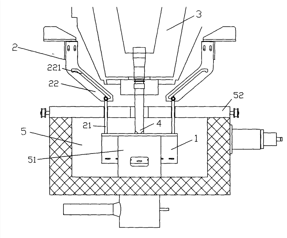
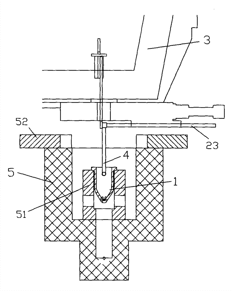
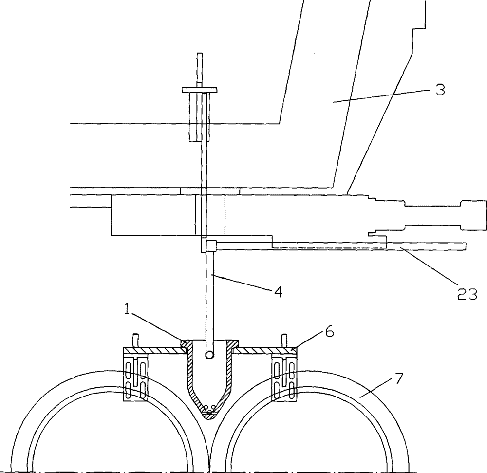
[0037] see Figure 1 ~ Figure 3 , which shows the first embodiment of the present invention. The flow distributor 1 is installed at both ends of the bottom of the tundish car 3 through the hanging mechanism 2, the distributor 4 is installed at the bottom of the tundish car 3, the distributor 4 is inserted into the flow distributor 1, and the tundish car 3 carries the flow distributor 1 and distribution The device 4 moves up and down together;

[0038] The hanging mechanism 2 includes a suspension rod 21 and a fixed bracket 22; the upper end of the fixed bracket 22 is fixed at both ends of the bottom of the tundish car 3, and the fixed bracket 22 is provided with an inclined chute 221 that enables the upper end of the suspension rod to move up and down; The flow distributor 1 is set at the lower end of the boom 21; after reaching the casting position, the boom 21 hangs the flow distributor 1 and then descends, and adjusts the upper and lower positions of the tundish car 3, so th...

Embodiment 2

[0045] see Figure 4 ~ Figure 7 , which shows the second embodiment of the present invention. Another structural form of the hanging mechanism 2 according to the present invention includes two fixed frames 24, two pairs of hanging claws 25, two gear sets 26, and a movable slide plate 27; the fixed frames 24 are installed on both sides of the tundish car 3, fixed The frame 24 is provided with a track 241 for lifting the upper end of the hanging claw 25; each pair of hanging claws 25 is cross-connected by a central axis; the gear set 26 is arranged on the fixed frame 24, and the moving slide plate 27 is a T-shaped structure, and the side of the middle boss It is a rack structure, which cooperates with the gear set 26 gears, and the other end is connected to the central shaft 251 between the two pairs of hanging claws 25;

[0046] The tundish car 3 has an independent hydraulic lifting mechanism, which moves up and down together with the hanging mechanism 2 to adjust the up and d...


PUM


Abstract

The invention discloses a method for hoisting, roasting and casting a strip continuous casting flow distribution device. The method comprises the following steps that: 1) the flow distribution device is arranged at two ends of the bottom of a tundish vehicle through a hanging mechanism, a distributor is arranged at the bottom of the tundish vehicle and inserted into the flow distribution device, and the tundish vehicle drives the flow distribution device and the distributor to move up and down; 2) during roasting, a roasting pit has an independent temperature control system, and gas nozzles are arranged on the periphery inside the roasting pit; 3) hot charging is performed after roasting is finished; and 4) after the tundish vehicle, the hanging mechanism and the flow distribution device reach a casting position, the hanging mechanism hangs the flow distribution device to descend together, and places the flow distribution device on a bracket of the flow distribution device of the roasting pit, and then the hanging mechanism is separated from the flow distribution device for molten steel to inject. By the method, the time of strip continuous casting hot charging process can be effectively reduced, so that temperature drop of the flow distribution device in the process of hot charging is reduced, the problem that cold steel is easy to form when the high-temperature molten steel is contacted with the flow distribution device can be effectively avoided, and the success rate of strip continuous casting pouring is improved; the method is convenient to operate and the hot charging step is convenient to implement at the same time; and a heating furnace can also be saved and field resources are greatly saved.

Description

technical field [0001] The invention relates to the field of thin strip continuous casting, in particular to methods for hoisting, baking and casting of a suspender type flow distributor for thin strip continuous casting. Background technique [0002] In recent years, domestic and foreign research activities on the development of direct casting technology for steel strip (that is, near-net-shape processing technology for strip steel) have become more and more active, and the fastest growing technology is twin-roll thin strip continuous casting technology. The twin-roll strip continuous casting technology was first proposed by Henry Bessemer in 1865 (US Patent: 49053). Thin strip continuous casting integrates continuous casting, rolling, and even heat treatment into one process, so that the produced thin strip can be rolled into industrial products at one time, which greatly simplifies the production process from molten steel to steel strip and shortens the production process...

Claims


Application Information

Patent Timeline
Patent Type & Authority Patents(China)
IPC IPC(8): B22D11/16
Inventor 方园张健吴建春于艳顾龙发
Owner BAOSHAN IRON & STEEL CO LTD
Learn More