
Petroleum coke powder combustion transporting device for improved industrial furnace

A petroleum coke powder and conveying device technology, which is applied in the direction of conveying bulk materials, conveyors, combustion methods, etc., can solve the problem of reducing the pressure of gas source conveying, and achieve the effect of reducing power consumption and saving energy

Inactive Publication Date: 2011-05-04
刘孝武
View PDF4 Cites 6 Cited by
  • Summary
  • Abstract
  • Description
  • Claims
  • Application Information

AI Technical Summary

Problems solved by technology

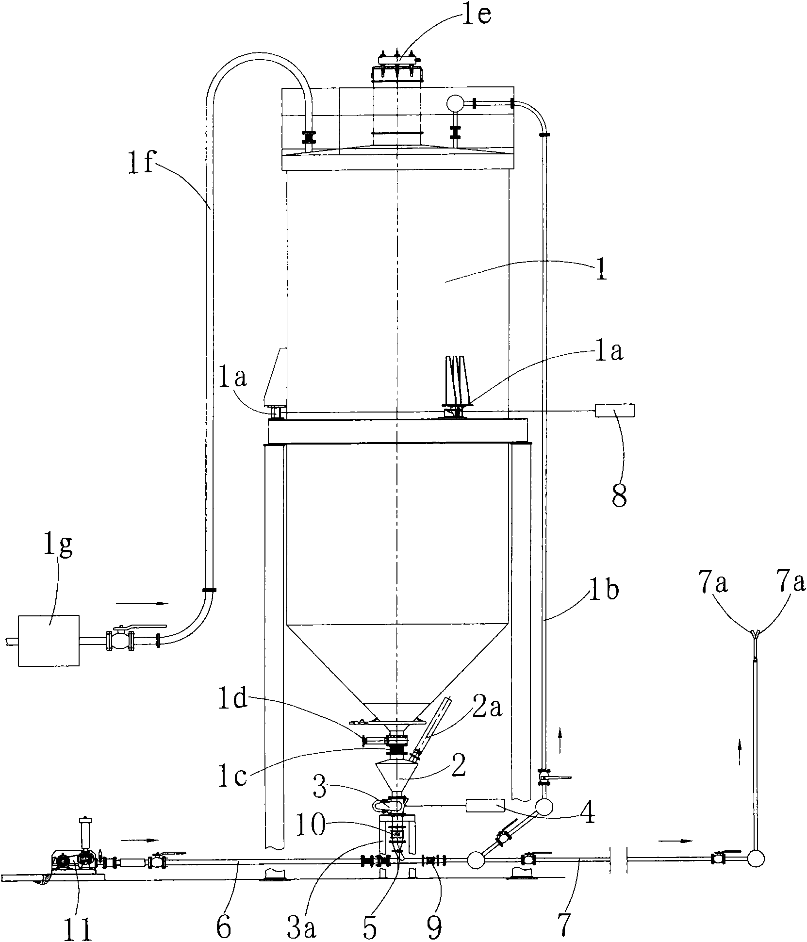
[0006] After adopting the above technical scheme, the conveying pump in the prior art is replaced with a ventilating balance chamber, through which the pressure difference between the inlet and outlet of the feeder can be balanced and overcome to ensure the smooth operation of the feeder. In this way, the petroleum coke powder in the silo is supplied to the feeder by means of a ventilated balance chamber and then directly transported to the pneumatic fluidization chamber. Therefore, there is no problem of leakage and environmental pollution, and there is no power consumption of the conveying pump, and no Noise will be generated; the outlet of the pneumatic fluidization chamber uses normal pressure air, so that in the outlet of the pneumatic fluidization chamber, petroleum coke powder and normal pressure air are mixed to form an aerosol two-phase fluid, and the delivery pressure of the air source is effective. Reduced, compared with the compressed air used in the existing technology, the power consumption is reduced by nearly half, which greatly saves energy

Method used

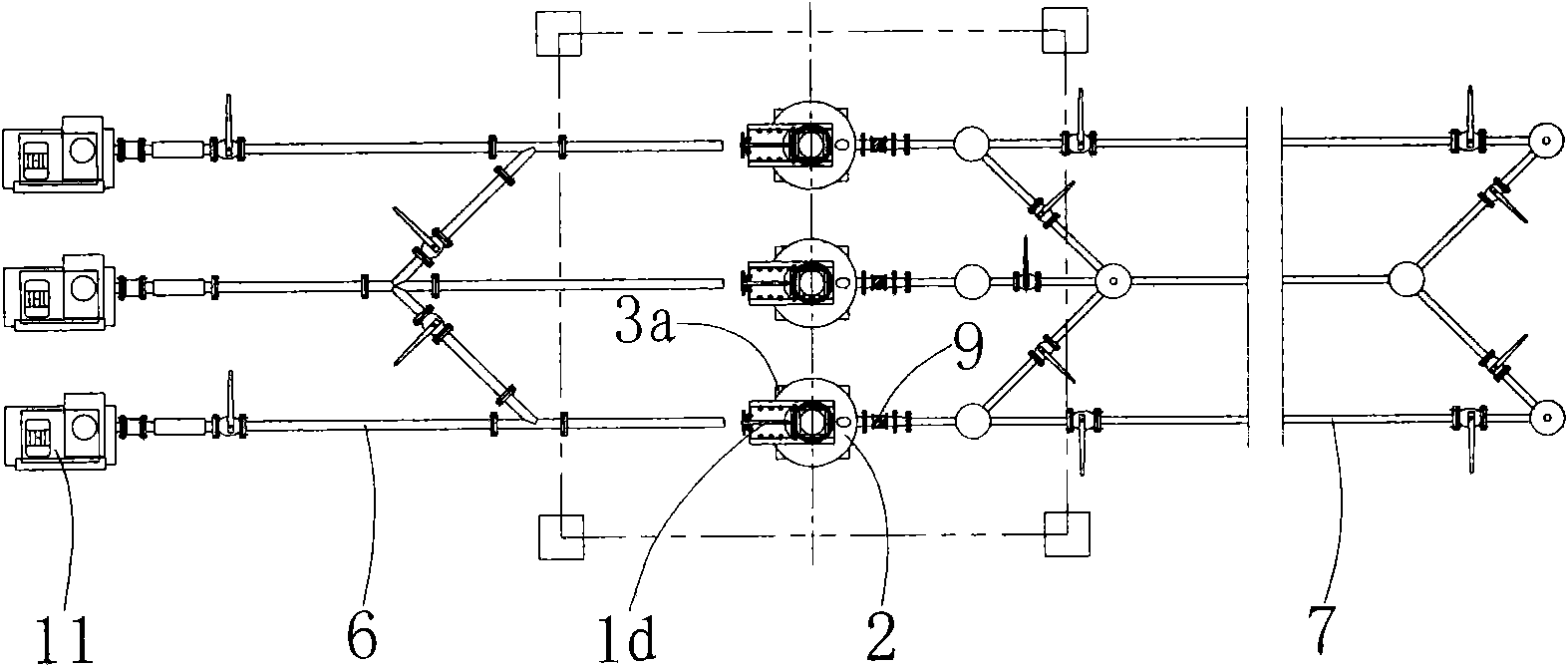
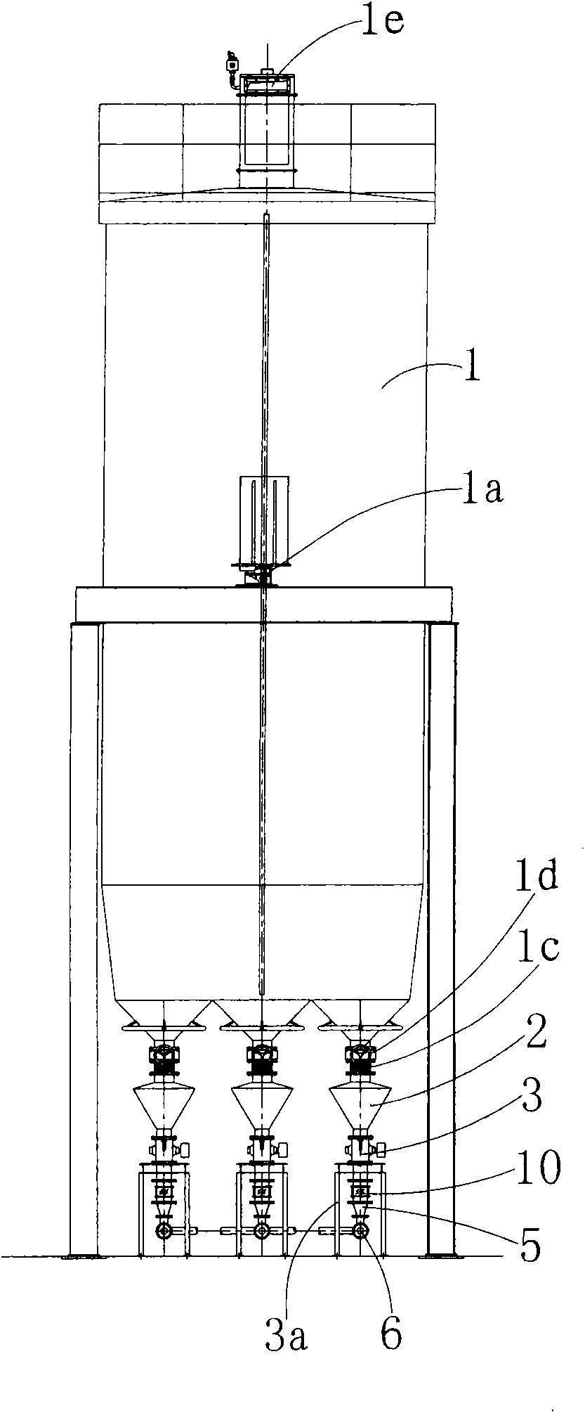

Image

  • Petroleum coke powder combustion transporting device for improved industrial furnace
  • Petroleum coke powder combustion transporting device for improved industrial furnace
  • Petroleum coke powder combustion transporting device for improved industrial furnace

Examples


Embodiment Construction

[0014] The present invention will be described in further detail below by way of implementation and accompanying drawings:

[0015] For the sake of succinct explanation, figure 2 Removed the silo 1 and its corresponding accessories, air pipe 2a, feeder controller 4, weighing controller 8, image 3 Removed filter 1g, feeder controller 4, weighing controller 8, blower 11.

[0016] see figure 1 , the present invention provides an improved petroleum coke powder combustion conveying device for industrial kilns, which includes a silo 1, a ventilating balance chamber 2, a feeder 3, a feeder controller 4, a pneumatic fluidization chamber 5, a regular Compressed air delivery pipeline 6 and fuel delivery pipeline 7.

[0017] The silo 1 is used to temporarily store petroleum coke powder. The feed pipe 1f with a filter 1g is connected to the top of the silo 1. The upper end of the silo 1 is equipped with a dust collector 1e, and three load cells 1a are evenly distributed in the middle...


PUM


Abstract

The invention relates to a petroleum coke powder combustion transporting device for an improved industrial furnace, comprising a material cabinet, a feed machine, a feed machine controller, a pneumatic fluidifying cavity and a fuel transport pipeline; a ventilation balance room is arranged at the discharge port on the lower end of the material cabinet; the upper end of the ventilation balance room is connected with a gas pipe; the lower part of the ventilation balance room is communicated with the feed port of the feed machine; the discharge port of the feed machine is communicated with the pneumatic fluidifying cavity; the feed machine controller is used for controlling the concrete operation of the feed machine; the upper stream on the export of the pneumatic fluidifying cavity is connected with a normal-pressure air transport pipeline and the lower stream on the export of the pneumatic fluidifying cavity is connected with the fuel transport pipeline. The ventilation balance room is arranged on the discharge port on the lower end of the material cabinet through an inserting plate valve and a corrugated pipe communicated up and down. A vision lens is arranged between the discharge port of the feed machine and the pneumatic fluidifying cavity; and the vision lens is arranged at the lower stream of the fuel transport pipeline close to the export of the pneumatic fluidifying cavity. The device has the advantages of energy saving, environment protection and low noise.

Description

technical field [0001] The invention relates to a conveying device in a combustion system of petroleum coke powder, which is mainly suitable for the combustion system of a glass melting kiln, and is also suitable for the combustion system of industrial kilns such as cement, ceramics, and boilers. technical background [0002] Currently, petroleum coke powder is commonly used as fuel in industrial kilns. [0003] The Chinese utility model patent specification with the patent number 200720053188.1 discloses a "petroleum coke powder combustion conveying device for industrial kilns". With this device, the petroleum coke powder does not need to be liquefied, and is directly transported to the spray gun in the form of dry powder through compressed air fluidization Combustion saves the existing pulping process and equipment, overcomes the energy loss and kiln corrosion caused by adding water or oil to liquefy, saves the cost of purchasing additives, improves the level of automation...

Claims


Application Information

Patent Timeline
Patent Type & Authority Applications(China)
IPC IPC(8): B65G53/16B65G53/34B65G53/40B65G53/66F23K5/00F23N1/00
Inventor 刘孝武
Owner 刘孝武
Learn More