
Micromechanical structure and method for manufacturing micromechanical structure

一种微机械结构、电极结构的技术,应用在制造微观结构装置、微结构技术、微观结构装置等方向,能够解决不能表面结构差分式分析处理等问题,达到提高偏移量或零点稳定性、实现应力去耦合、好信噪比的效果

Active Publication Date: 2011-04-27
ROBERT BOSCH GMBH
View PDF7 Cites 10 Cited by
  • Summary
  • Abstract
  • Description
  • Claims
  • Application Information

AI Technical Summary

Problems solved by technology

The disadvantage of this arrangement is that the offset of the surface structure cannot be analyzed differentially

Method used


Image

  • Micromechanical structure and method for manufacturing micromechanical structure
  • Micromechanical structure and method for manufacturing micromechanical structure
  • Micromechanical structure and method for manufacturing micromechanical structure

Examples


Embodiment Construction

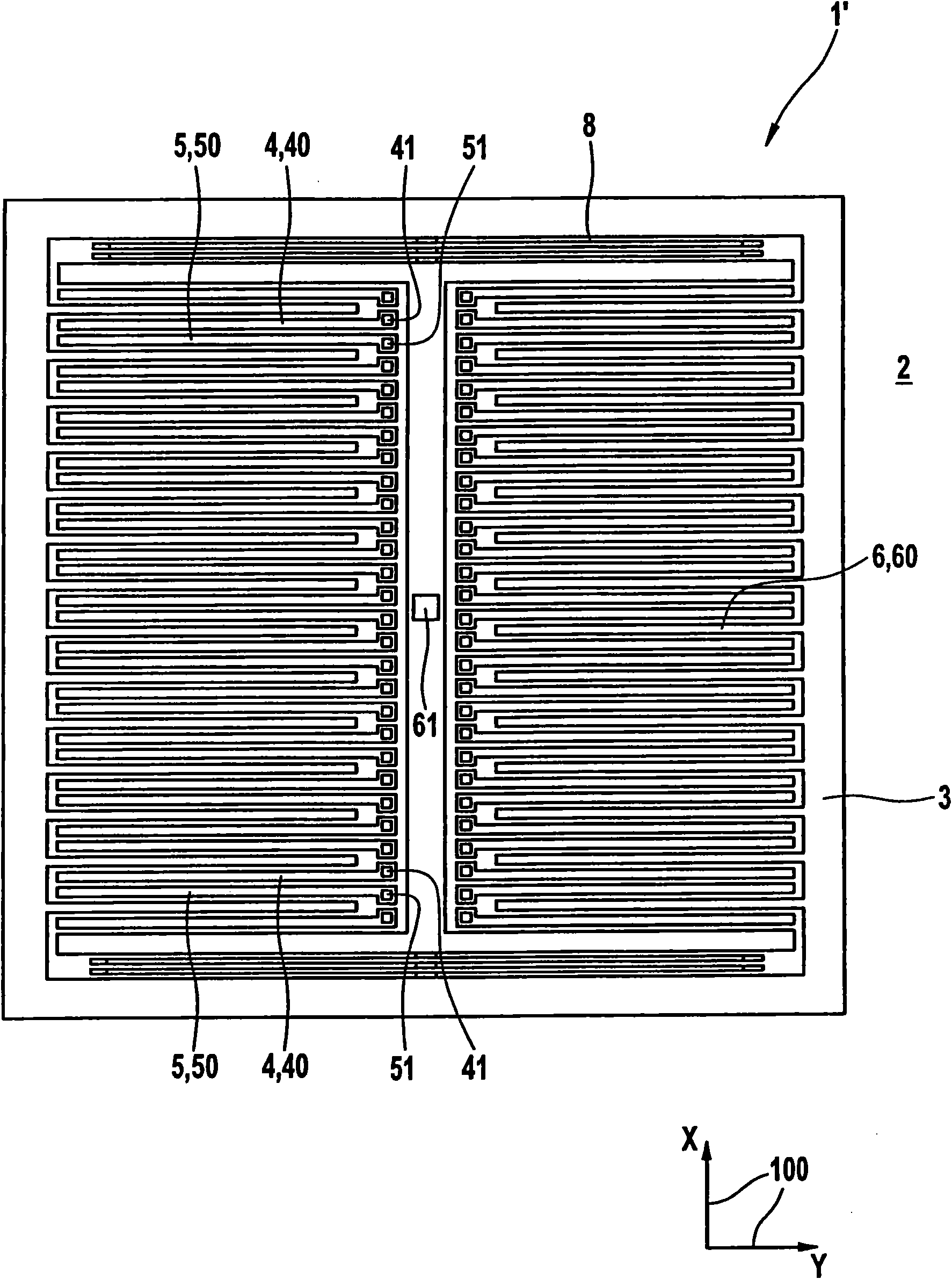
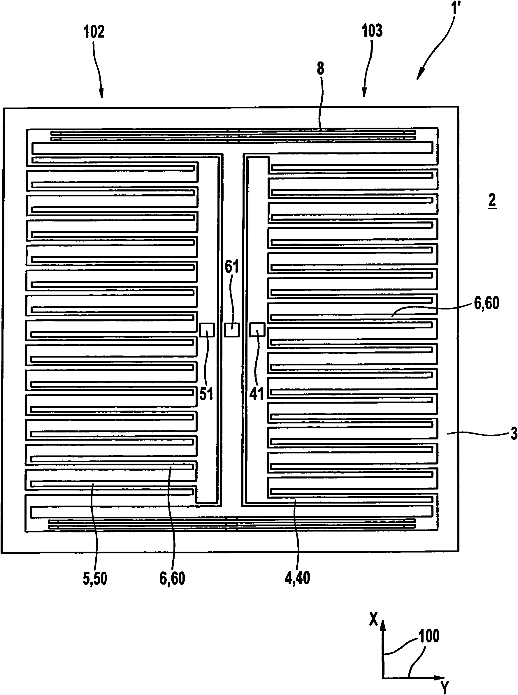
[0021] exist figure 1A schematic top view of a micromechanical structure 1' according to the prior art is shown in . The micromechanical structure 1' comprises a substrate 2 having a main plane of extension 100 and a seismic mass 3 movable relative to the substrate 2. The seismic mass 3 is coupled via the spring element 8 to a third anchoring element 61, which is fixedly connected to the substrate 2 in the central region 7 of the micromechanical structure 1'. Seismic mass 3 also includes a counter-electrode structure 6 with third finger electrodes 60 . The micromechanical structure 1' also comprises a first and a second electrode structure 4,5. The first electrode structure 4 includes first finger electrodes 40 in the form of spanner arms, wherein each of the first finger electrodes 40 is fixed on the substrate 2 via its own first anchoring element 41 . The second electrode structure 5 includes second electrode fingers 50 in the form of spanner arms, wherein the second...


PUM


Abstract

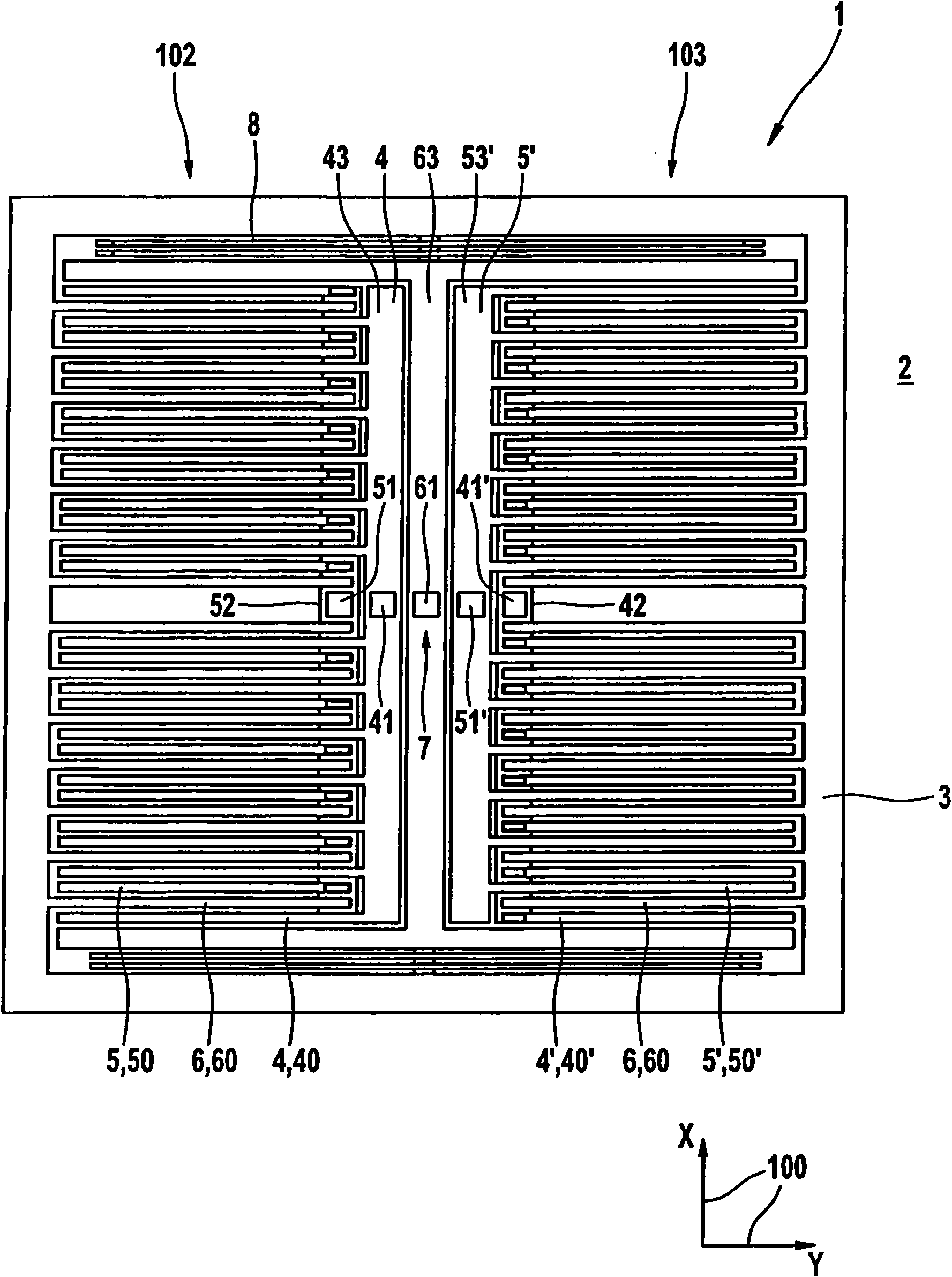
The invention relates to a micromechanical structure, including a substrate which has a main plane of extension, a seismic mass movable relative to the substrate along a first direction parallel to the main plane of extension, a first electrode structure connected to the substrate and a second electrode structure connected to the substrate. The seismic mass includes a counterelectrode structure, third finger electrodes of which are situated between first finger electrodes of the first electrode structure and second finger electrodes of the second electrode structure along the first direction. The first electrode structure is fastened to the substrate by a first anchoring element in a central region of the micromechanical structure, and the second electrode structure is anchored to the substrate by a second anchoring element situated in the central region. The invention also relates to a method for manufacturing the micromechanical structure.

Description

technical field [0001] The invention relates to a micromechanical structure and a method for producing a micromechanical structure. Background technique [0002] Such micromechanical structures are generally known. For example, from document DE 196 39 946 A1, an acceleration sensor in the form of a micromechanical structural element is known, which is provided with a substrate with a surface and an integral surface structure, wherein the surface structure has movable electrodes, The movable electrodes are suspended on bending springs and are movable relative to the substrate, wherein the micromechanical structural element has fixed electrodes which are arranged opposite the movable electrodes and are immovable relative to the substrate, The surface structure is fastened to the surface with at least two anchoring regions and in other words extends at a distance from the surface, wherein the at least two anchoring regions have a transverse expansion relative to the surface mi...

Claims


Application Information

Patent Timeline
Patent Type & Authority Applications(China)
IPC IPC(8): B81B7/02B81B3/00B81C1/00G01P15/125
CPCG01P15/125B81B3/0072B81B2201/0235G01P15/0802G01P2015/0814Y10T29/49204
Inventor J·克拉森C·比尔霍夫
Owner ROBERT BOSCH GMBH
Learn More