Powered Mobility Device with Tilt Mechanism having Multiple Pivots

Active Publication Date: 2016-10-20
OGO TECH LTD
View PDF6 Cites 4 Cited by
  • Summary
  • Abstract
  • Description
  • Claims
  • Application Information

AI Technical Summary

Benefits of technology

The mobility device described in the patent has a tilt mechanism that allows the seat to move forwards or backwards, with a secondary pivot located between the seat and the shafts that allows for greater control and offset of weight transfer. The device also has a weight displacement sensor that controls the speed of the device based on the rate of weight displacement caused by the user's movement of the seat. This allows for increased control and efficiency of the mobility device.

Problems solved by technology

A problem with existing mobility devices such as wheelchairs is that they are not easily operable by a user, especially those users that have significant loss or impaired movement of their limbs (arms and legs).
Also most all wheelchairs are not suitable to be used on all surface types.
They are not able to be used easily or effectively on soft surfaces such as lawns or undulating surfaces, i.e. they are not able to be used “off road”.
They are prone to get stuck and require assistance of others to be able to go “off road”.
It is known to have wheel chairs that are controlled by the weight placement of the user, however these are not suitable for providing fine control of such movement in places where required (such as a crowded place or in a shop) or are not suitable for “off road” use.

Method used


Image

  • Powered Mobility Device with Tilt Mechanism having Multiple Pivots
  • Powered Mobility Device with Tilt Mechanism having Multiple Pivots
  • Powered Mobility Device with Tilt Mechanism having Multiple Pivots

Examples


Embodiment Construction

)

[0035]The following description will describe the invention in relation to preferred embodiments of the invention, typically a powered wheelchair, that is able to be steered with or without the use of hands The invention is in no way limited to these preferred embodiments as they are purely to exemplify the invention only and that possible variations and modifications would be readily apparent without departing from the scope of the invention.

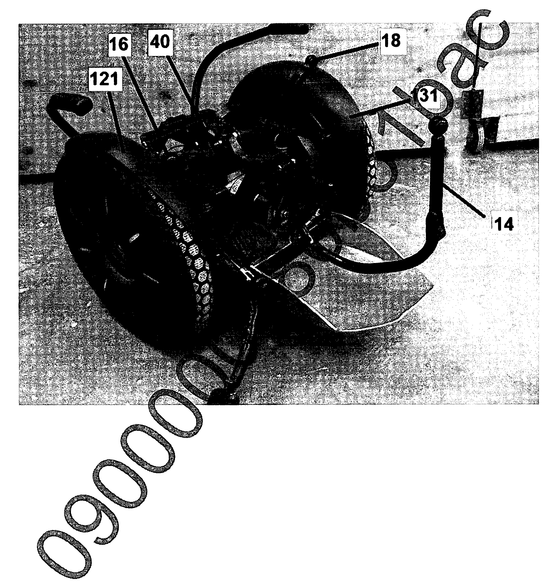
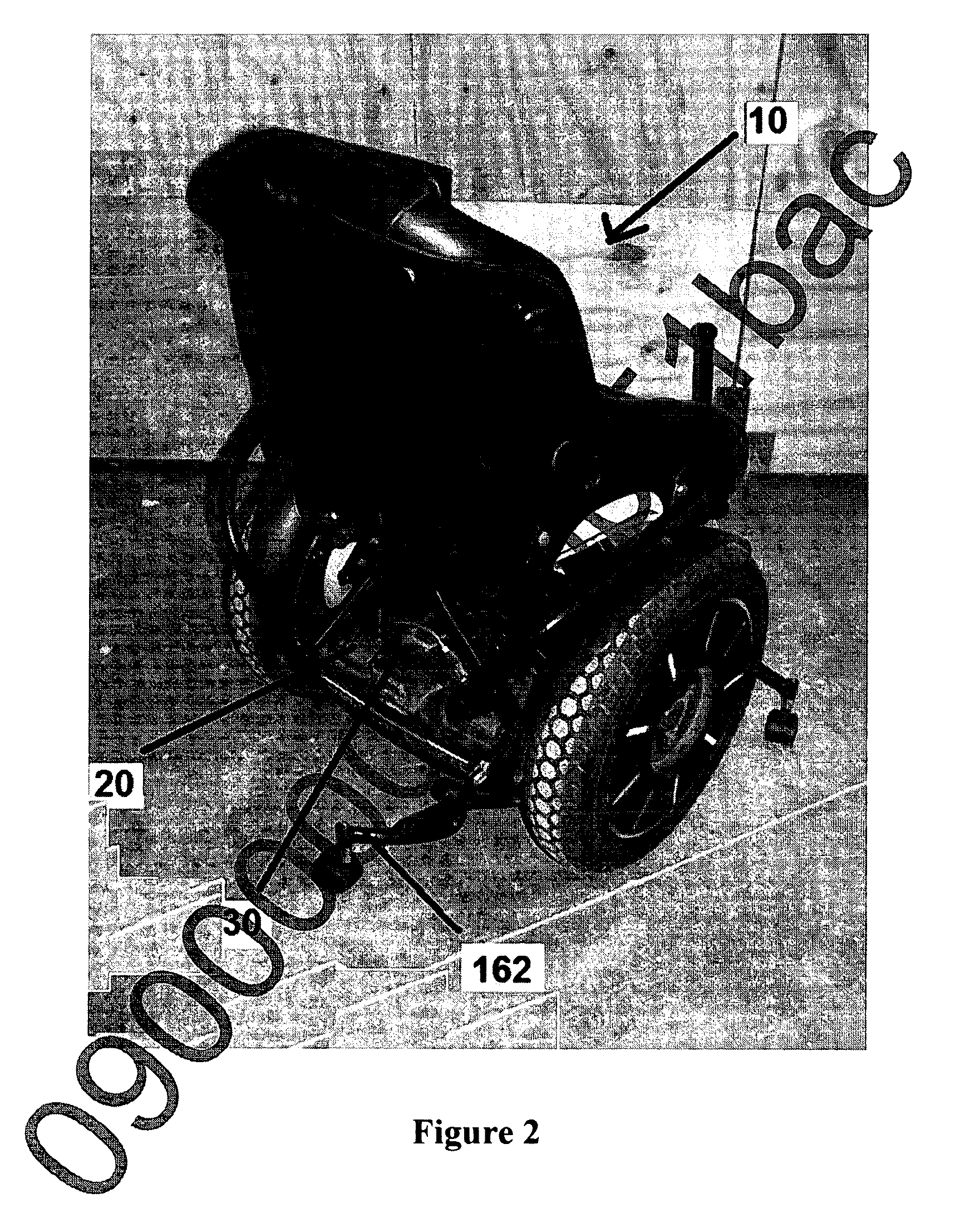
[0036]The mobility device shown in the FIGS. 1 to 5 is to a preferred embodiment of a wheelchair. FIGS. 1 to 3 show differing views of the wheelchair 100 and FIGS. 4 & 5 show the details of the multi pivot arrangement for the wheelchair 100. The wheelchair 100 is a powered wheelchair 100 and is typically powered by electric battery, however other known modes of powering the wheelchair 100 are envisaged.

[0037]The wheelchair 100 is able to be driven on road and off-road. The wheelchair 100 is able to be maneuvered and steered with or without the...


PUM


Abstract

A powered wheelchair 100 with a tilt mechanism having multiple pivots that allows the wheelchair 100 to be driven and steered with or without the use of hands. The wheelchair 100 has two spaced apart drive wheels 101, each mounted to a separate shaft 104 that is independent of the other drive wheel. A drive controller drivingly coupled to the shafts 104 and the drive controller is housed within a base 102 that is pivotally situated on the shafts 104. A seat 103 mounted on a tilt mechanism enables the seat to tilt in a forward, backward, left and right direction as a result of the user displacing their body weight in either of those directions. The tilt mechanism includes three pivots, a primary pivot P1, secondary pivot P2 and tertiary pivot P3. The primary pivot P1 pivotally connects the base 102 to the shafts 104. The secondary pivot P2 is situated above and adjacent the base 102 so that the respective ends of the rod 105 are pivotally connected to the base 102.

Description

RELATED APPLICATIONS[0001]This application is a continuation in part application which claims priority to U.S. non-provisional application Ser. No. 14 / 373,354 filed on Jul. 19, 2014 and New Zealand patent application number 706881, filed on Apr. 10, 2015 and incorporated herewith by reference in its entirety.FIELD OF THE INVENTION[0002]The invention relates to a powered mobility device with tilt mechanism having multiple pivots, typically a powered wheelchair, which is able to be steered with or without the use of hands.BACKGROUND OF INVENTION[0003]A problem with existing mobility devices such as wheelchairs is that they are not easily operable by a user, especially those users that have significant loss or impaired movement of their limbs (arms and legs).[0004]Also most all wheelchairs are not suitable to be used on all surface types. They are not able to be used easily or effectively on soft surfaces such as lawns or undulating surfaces, i.e. they are not able to be used “off road...

Claims


Application Information

Patent Timeline
IPC IPC(8): A61G5/04A61G5/10
CPCA61G5/041A61G5/1056A61G2005/1051A61G5/04A61G5/10A61G2203/10A61G2203/30A61G5/1089A61G5/1051A61G5/128A61G5/1062A61G2203/14A61G2203/44B62K3/00B62K11/007B62K2204/00B62J45/4151
Inventor HALSALL, KEVIN THOMAS
Owner OGO TECH LTD
Why Eureka
Try Eureka