


Quick Research
Generate reliable direction feasibility study reports for your R&D in just a few steps.

Technical Q&A
Discover and master advanced knowledge NOW. Basics, ideas, possibilities, all at once.

Find Solutions
As an expert in R&D theories, this can generate solutions to your technical problems instantly.

Evaluate Feasibility
Analyze your overall solution with one click, know your potential R&D risks in advance.

Monitor Landscape
Get weekly tech updates, stay abreast of the latest tech innovations and key insights.
Film pneumatic punching method and corresponding equipment
A film and punching technology, which is applied in the field of film air pressure punching and corresponding equipment, can solve the problems of complex process, electrolyte pollution, high cost, etc., and achieve the effect of no burr in the cut, low cost and smooth chip removal
- Summary
- Abstract
- Description
- Claims
- Application Information
AI Technical Summary
Problems solved by technology
Method used
Image


Examples
Embodiment approach 1
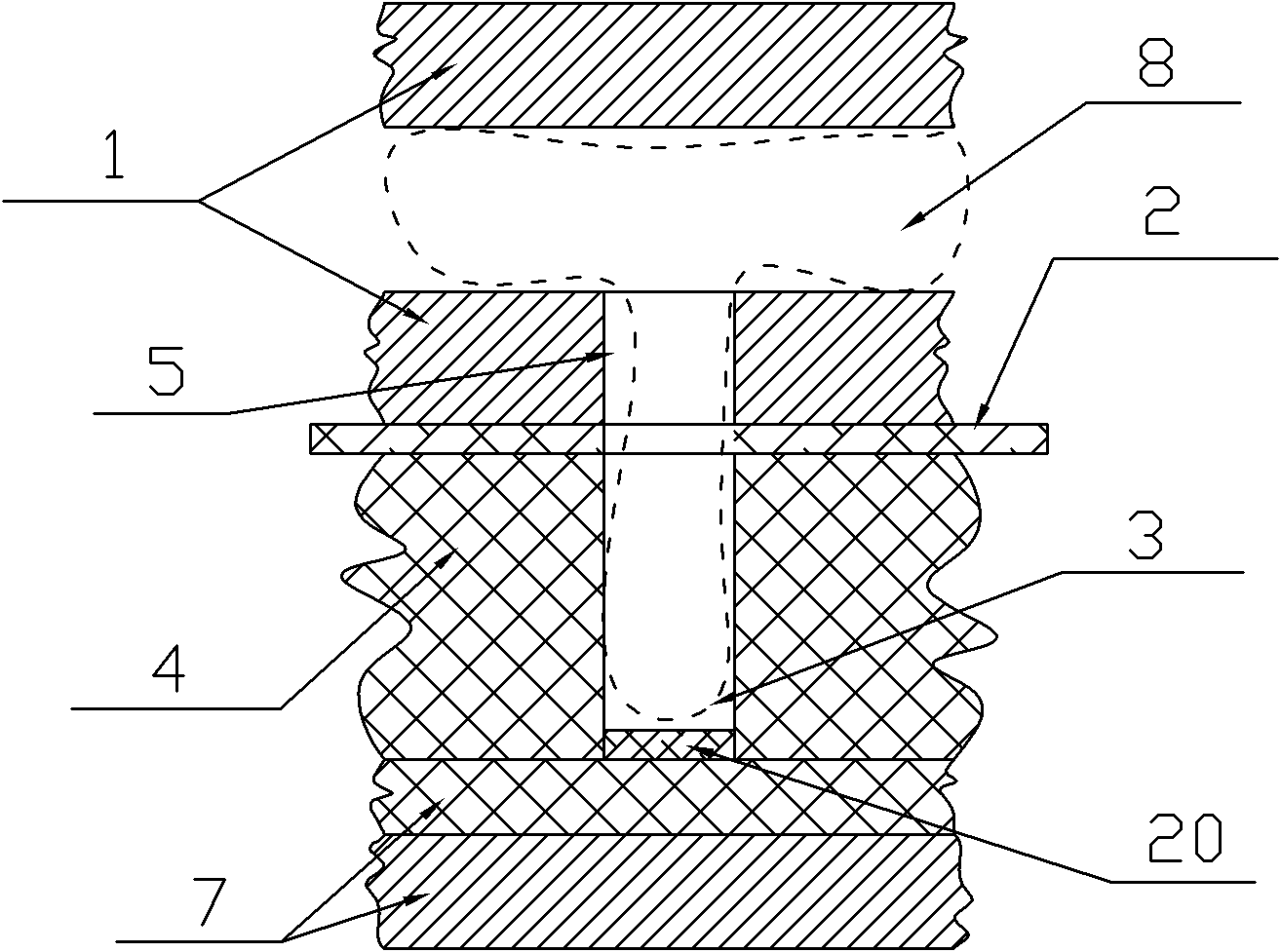
[0036] Implementation mode one: if Figure 1-3 Shown, this thin film air pressure punching method comprises the following steps:
[0037] ①. Use the upper mold 1 to press the film 2 tightly on the lower mold 4 with multiple air cavity holes 3. On the lower surface of the upper mold 1, there are positions opposite to the air cavity holes 3, and the size and number are the same as the air cavity holes 3. The same through-holes 5, the above-mentioned through-holes 5 are all communicated with an air intake chamber 6, and the air intake chamber 6 is communicated with a high-pressure air source through an air valve, and the upper mold 1, the lower mold 4 and the film 2 are all air-tight; Seal the lower end of the air cavity hole 3 with a movable seal 7;
[0038] ②, and then pass high-pressure gas 8 into the air inlet cavity 6 of the upper mold 1, and the high-pressure gas 8 breaks through the film at each air cavity hole 3 and enters the air cavity hole 3 to realize punching;
[0...
Embodiment approach 2
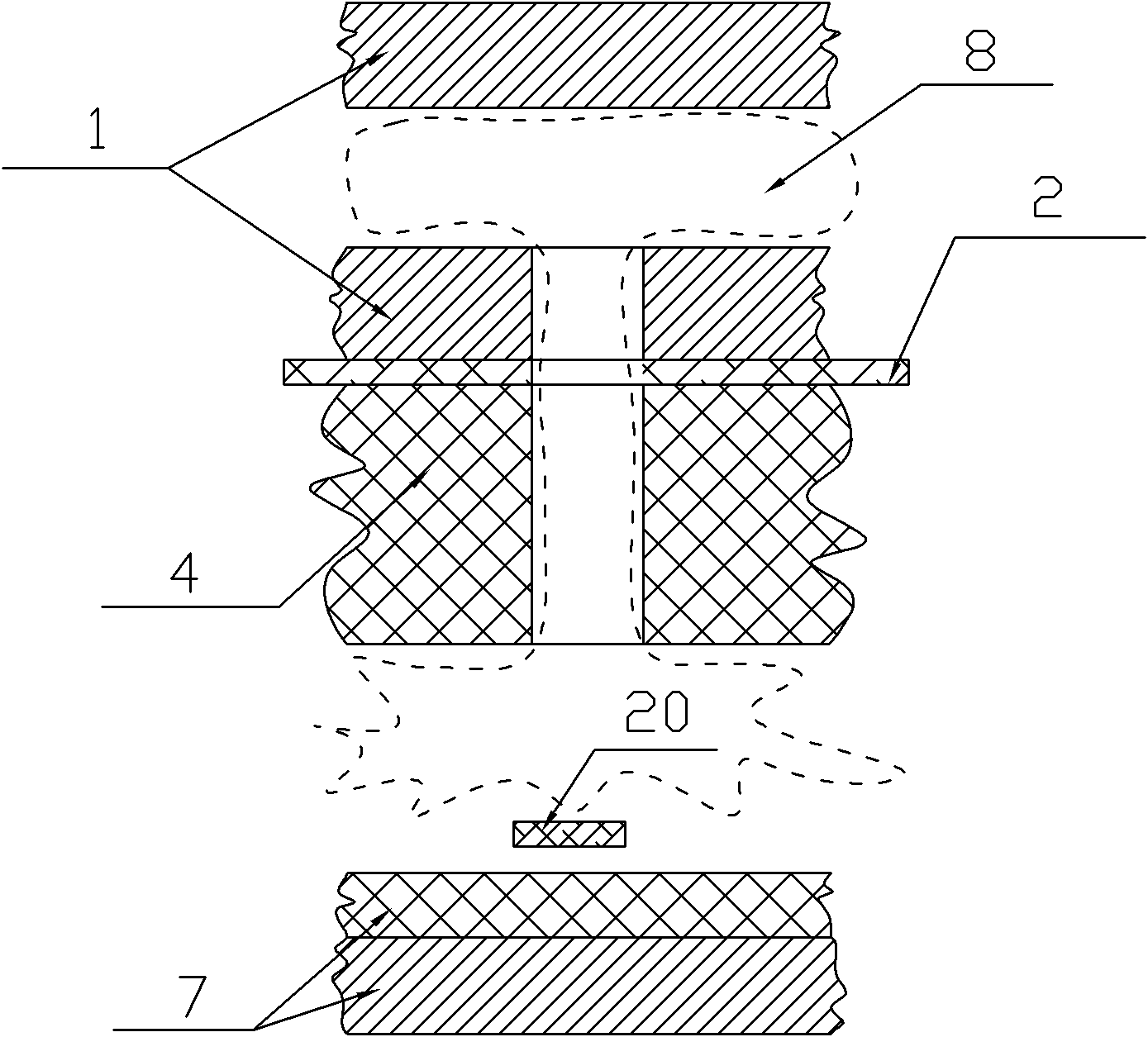
[0041] Implementation mode two: if Figure 4-6 Shown: the film punching equipment of the present invention includes an air compressor (not shown in the figure), a lower die 4, an upper die 1 and a movable seal 7, wherein the lower die 4 and the upper die 1 are respectively arranged on the upper and lower sides of the film 2 , the lower mold 4 is provided with a plurality of air cavity holes 3, and the upper mold 1 is arranged on a lifting table 9, and the lower surface thereof is provided with a position opposite to the air cavity holes 3, the size and number of which are the same as those of the air cavity holes 3 The same through holes 5, above-mentioned through holes 5 communicate with an air intake cavity 6, the air intake cavity 6 communicates with the high-pressure gas outlet of the air compressor through an air valve, and the movable seal 7 is arranged on the lower mold 4 Below, and be equipped with driving cylinder, can block the air chamber hole 3 lower ends.
[0042...
Embodiment approach 3
[0046] Embodiment 3: The upper mold 1 is provided with an air inlet chamber 7 opposite to the area where the air cavity hole 3 is located. The air inlet chamber 7 communicates with a high-pressure air source through an air valve. The rest of the steps are similar to Embodiment 1, omitted.
PUM
 Abstract
Description
Claims
Application Information
 - R&D Engineer
- R&D Manager
- IP Professional
- Industry Leading Data Capabilities
- Powerful AI technology
- Patent DNA Extraction
Browse by: Latest US Patents, China's latest patents, Technical Efficacy Thesaurus, Application Domain, Technology Topic, Popular Technical Reports.
© 2024 PatSnap. All rights reserved.Legal|Privacy policy|Modern Slavery Act Transparency Statement|Sitemap|About US| Contact US: help@patsnap.com