Eureka AIR delivers breakthrough ideas for toughest innovation challenges, trusted by R&D personnel around the world.

Novel stentering setting machine

A tenter setting machine, a new type of technology, is used in textiles and papermaking, fabric surface trimming, fabric elongation and other directions, which can solve the problems of inability to accurately adjust, limited angle, oil spillage, etc., to ensure the quality of tenter setting, The effect of reducing heat loss and simple structure

Inactive Publication Date: 2014-05-14
ZHEJIANG RILI INDAL
View PDF5 Cites 0 Cited by
  • Summary
  • Abstract
  • Description
  • Claims
  • Application Information

AI Technical Summary

Problems solved by technology

Its disadvantages are: the current adjustment is generally carried out through gears and racks, which cannot be adjusted accurately, affects production, and cannot meet the better tentering effect of different fabrics
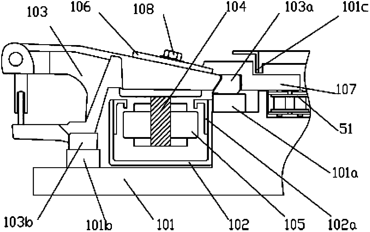
[0003] At the same time, the existing cloth clips are driven by chains, which will cause oily dirt to flow onto the cloth and affect the quality of the cloth. At the same time, the position of the existing cloth clips is fixed and cannot be adjusted, which cannot meet the needs of different cloth and reduce the tenter effect of the cloth.
[0004] Moreover, the hot exhaust gas of the oven of the existing stenter setting machine is generally directly discharged outward, and the heat of the hot exhaust gas can be reused to waste heat energy;
[0005] In the expanding device of the existing stenter setting machine, the adjustable angle of the two expanding rollers is limited, so that the adjustable range of the wrapping angle between the expanding roller and the fabric is small, and the two expanding rollers cannot be adjusted at the same time.

Method used


Image

  • Novel stentering setting machine
  • Novel stentering setting machine
  • Novel stentering setting machine

Examples


Embodiment

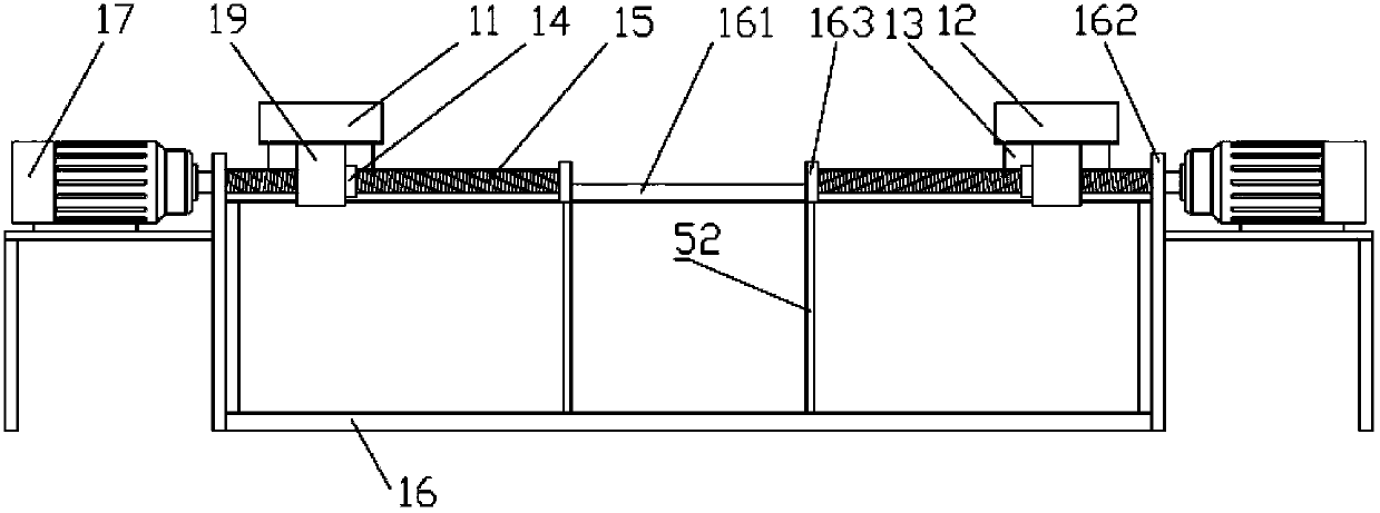
[0034] Example: see Figures 1 to 10 As shown, a new type of stenter setting machine includes a guide device 10, a traction mechanism 20, an operating table 30 and a cloth drop device 40, the guide device 10 is in front of the traction mechanism 20, the cloth fall device 40 is behind the traction mechanism 20, and the operation table 30 is placed between the guide device 10 and the traction mechanism 20, the expanding device 4 is arranged on the guide device 10, the traction mechanism 20 includes a feeding track 1, an oven 2 and a heat exchange device 3, the feeding track 1 passes through the oven 2, and the heat exchange The device 3 is arranged above the oven 2, the exhaust gas outlet pipe 21 of the oven 2 communicates with the exhaust gas inlet pipe 31 of the heat exchange device 3, and the hot air outlet pipe 32 of the heat exchange device 3 communicates with the hot air inlet pipe 22 of the oven 2;

[0035] Feeding track 1 comprises two left guide rails 11 and right guide...


PUM


Abstract

The invention provides a novel stentering setting machine comprising a guide device, a drawing mechanism, an operation platform and a cropping device, wherein the cropping device is arranged behind the drawing mechanism and the operation platform is placed between the guide device and the drawing mechanism; the drawing mechanism comprises a feeding rail, an oven and a heat exchange device; the feeding rail passes through the oven and the heat exchange device is arranged above the oven; a waste gas outlet pipe of the oven is communicated with a waste gas inlet pipe of the heat exchange device; a hot air outlet pipe of the heat exchange device is communicated with a hot air inlet pipe of the oven; a guide rail adjusting device is additionally arranged between two guide rails, so that the distance between a left guide rail and a right guide rail can be accurately adjusted and each guide rail is respectively adjustable; the novel stentering setting machine is suitable for machining a plurality of types of cloth; meanwhile, cloth tongs slide on graphite and do not generate oil stains; the two connected cloth tongs can be finely adjusted to ensure the stentering setting quality; and an adjustable range of a wrap angle of spreading rolls and a textile is large and the two spreading rolls can be adjusted, so that the spreading effect is good.

Description

Technical field: [0001] The invention relates to the technical field of a stenter setting machine, and more specifically relates to a novel stenter setting machine. Background technique: [0002] The stenter setting machine is equipped with two guide rails, which are left-right symmetrical, and the cloth clips on the two guide rails hold the cloth for stenter setting. The guide rails of the existing stenter setting machine are driven by a motor to adjust the distance between the two guide rails, and the motors are generally fixed at both ends of the guide rails. Its shortcoming is: the conventional adjustment is generally carried out through gears and racks, which cannot be adjusted accurately, affects production, and cannot meet the better tentering effect of different fabrics. [0003] At the same time, the existing cloth clips are driven by chains, which will cause oily dirt to flow onto the cloth and affect the quality of the cloth. At the same time, the existing cloth ...

Claims


Application Information

Patent Timeline
Patent Type & Authority Patents(China)
IPC IPC(8): D06C3/06
Inventor 李勇吕磊陈传
Owner ZHEJIANG RILI INDAL
Why Eureka
Eureka Blog
Learn More