Flotation machine stator and rotor production device

A flotation machine stator and production device technology, applied in spraying devices, devices for coating liquid on the surface, dryers, etc., can solve the problems of lower production efficiency, low cleaning efficiency, no rotor and stator, etc., and achieve improved Efficiency, ease of spraying effect

Active Publication Date: 2020-08-25
迁安信润和机械设备有限公司
View PDF10 Cites 0 Cited by
  • Summary
  • Abstract
  • Description
  • Claims
  • Application Information

AI Technical Summary

Problems solved by technology

[0003] The stator and rotor are important components of flotation equipment. Due to the long-term working environment in the state of liquid particles, the surface of the stator and rotor is severely eroded and worn, and the increase in the inner size affects the flotation effect and is scrapped. In the flotation machine When the stator and rotor are produced, it is necessary to spray nickel-based tungsten carbide powder on the surface of the stator and rotor. The corrosion resistance and hardness of the rotor and stator are improved through the nickel-based tungsten carbide powder. Before spraying the stator and rotor, it is generally necessary to manually spray the rotor and rotor. The oil stain on the surface of the stator is cleaned, the cleaning efficiency is low, and there is no special drying device for the rotor and the stator, which also reduces the overall production efficiency. When spraying the rotor and the stator, it is necessary to carry out special clamping for the rotor and the stator. Therefore, in view of the above problems, a flotation machine stator and rotor production device is proposed

Method used


Image

  • Flotation machine stator and rotor production device
  • Flotation machine stator and rotor production device
  • Flotation machine stator and rotor production device

Examples


Embodiment 1

[0026] see Figure 1-6 , the present invention provides a technical solution:

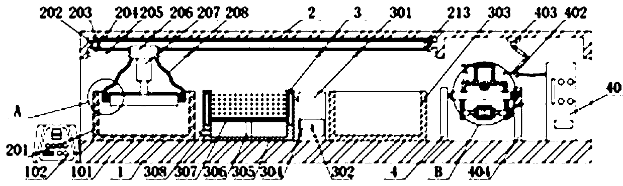
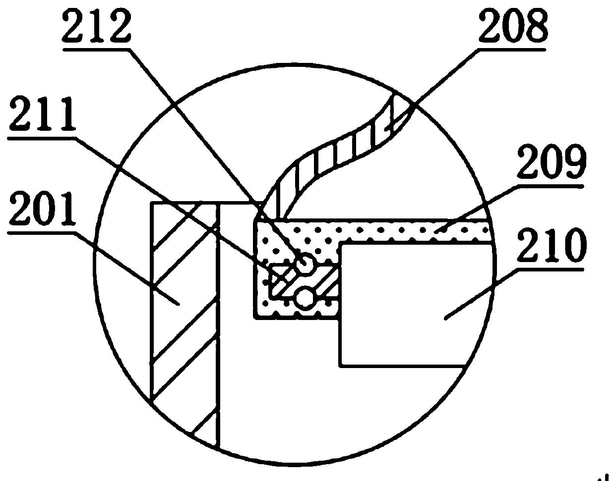
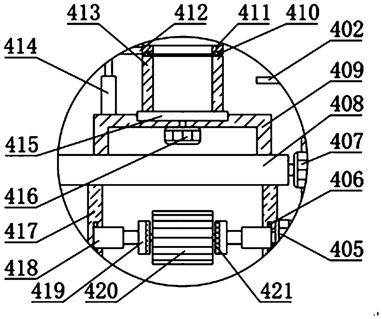
[0027]A flotation machine stator and rotor production device, including a main device 1, a cleaning device 2, a drying device 3 and a spraying device 4, one end of the main device 1 is fixedly connected with a cleaning device 2, and the right side of the cleaning device 2 is provided with a drying device. Drying device 3, and drying device 3 is fixedly connected with main device 1, and the right side of drying device 3 is provided with spraying device 4, and spraying device 4 is fixedly connected with main device 1, and main device 1 comprises fixing base 101, control cabinet 102, door plate 103 and first handle 104, one end of cleaning device 2 is fixedly connected with fixed seat 101, and the left end of fixed seat 101 is fixedly connected with control cabinet 102, and the front end of fixed seat 101 is connected with door plate 103 by hinge rotation, and the front end of door plate 103 The firs...

Embodiment 2

[0031] see Figure 1-6 , the present invention provides a technical solution:

[0032]A flotation machine stator and rotor production device, including a main device 1, a cleaning device 2, a drying device 3 and a spraying device 4, one end of the main device 1 is fixedly connected with a cleaning device 2, and the right side of the cleaning device 2 is provided with a drying device. Drying device 3, and drying device 3 is fixedly connected with main device 1, and the right side of drying device 3 is provided with spraying device 4, and spraying device 4 is fixedly connected with main device 1, and main device 1 comprises fixing base 101, control cabinet 102, door plate 103 and first handle 104, one end of cleaning device 2 is fixedly connected with fixed seat 101, and the left end of fixed seat 101 is fixedly connected with control cabinet 102, and the front end of fixed seat 101 is connected with door plate 103 by hinge rotation, and the front end of door plate 103 The firs...


PUM


Abstract

The invention relates to the technical field of flotation machine stator and rotor production, in particular to a flotation machine stator and rotor production device. The flotation machine stator androtor production device comprises a main device, a cleaning device, a drying device and a spraying device, wherein one end of the main device is fixedly connected with the cleaning device; the dryingdevice is arranged on the right side of the cleaning device; the drying device is fixedly connected with the main device; the spraying device is arranged on the right side of the drying device; and the spraying device is fixedly connected with the main device. In the flotation machine stator and rotor production device, a drying box and the like are arranged, and a rotor and a stator which are cleaned can be dried rapidly through the drying box, so that spraying on the surfaces of the rotor and the stator is facilitated. Through the arrangement of a swivel, limiting rings, compression rings and the like, when nickel-based tungsten carbide powder needs to be sprayed on the surface and the inner wall of the stator, the stator is placed between compression plates, then the stator is driven to rotate by the swivel, and meanwhile a spray head is driven to perform rapid spraying on the surface and the inner wall of the stator by a mechanical arm.

Description

technical field [0001] The invention relates to the technical field of stator and rotor production of flotation machines, in particular to a production device for stators and rotors of flotation machines. Background technique [0002] The flotation machine is suitable for the separation of non-ferrous and ferrous metals, and can also be used for the separation of non-metals such as coal fluorite and talc. The flotation machine is driven by the V-belt drive of the motor to rotate the impeller, which generates centrifugal action to form negative pressure. On the one hand, it sucks Sufficient air is mixed with the pulp. On the one hand, the pulp is mixed with the medicine, and at the same time, the foam is refined, so that the minerals adhere to the foam, float to the pulp surface, and then form mineralized foam. Adjust the height of the gate, control the liquid level, and make useful foam Scraped out by the scraper, as the flotation machine is more widely used, therefore, the ...

Claims


Application Information

Patent Timeline
Patent Type & Authority Applications(China)
IPC IPC(8): B05B16/20B05B13/02B05B13/04B05B13/06B05D3/04B08B3/12F26B9/06F26B21/00
CPCB05B13/0228B05B13/0285B05B13/0431B05B13/0645B05D3/0413B08B3/12B05B16/20F26B9/06F26B21/001F26B21/003F26B21/004
Inventor 邸福民刘庆新
Owner 迁安信润和机械设备有限公司
Why Eureka
Try Eureka