
Gas-sensitive absorption device based on hollow optical fibre

A hollow-core optical fiber and absorption device technology, which is applied in the field of gas sensing detection, can solve the problems of mechanical processing accuracy requirements, light source parallelism requirements, high price, high mechanical accuracy requirements, short optical path, etc., so as to improve the optical transmission efficiency and The effect of gas contact efficiency, low mechanical precision requirements, and simple device structure

Inactive Publication Date: 2011-04-20
JILIN UNIV
View PDF4 Cites 16 Cited by
  • Summary
  • Abstract
  • Description
  • Claims
  • Application Information

AI Technical Summary

Problems solved by technology

These gas chamber devices achieve high detection accuracy through the incident light passing through the gas chamber multiple times, but the requirements for machining accuracy, light source parallelism and price are also very high, so most of the instruments of this type of detection system can only be used In high-end laboratories and professional testing units
Using a single-pass absorption device, the optical path is short, and it is difficult to achieve high detection accuracy
[0004] At present, the spectral absorption devices that people study and use mainly have the following problems: (1) The mechanical precision of the devices is high, and a slight deviation will cause a very large error in the detection results
(2) Poor anti-vibration performance and high environmental requirements
(4) Professionals are required to perform regular maintenance and calibration

Method used


Image

  • Gas-sensitive absorption device based on hollow optical fibre
  • Gas-sensitive absorption device based on hollow optical fibre
  • Gas-sensitive absorption device based on hollow optical fibre

Examples


Embodiment 1

[0034] Embodiment 1: An example of the composition of a hollow-core optical fiber gas-sensitive absorption device

[0035] The air-sensitive absorption device (4) based on the hollow-core optical fiber of the present invention has the characteristics of simple structure and low precision requirement. In this embodiment, the end caps 8 and 9 are processed by a numerically controlled lathe, and the core component of the device, the hollow-core optical fiber, is a self-made hollow-core optical fiber.

[0036] The front end head (8) is processed by a numerically controlled lathe, and the base material is made of polyurethane plastic (PU), or chemically stable plastics or alloys such as polytetrafluoroethylene (PTFE) and polyethylene (PE). A polyurethane plastic (PU) rod with a diameter of 16mm is selected, and the length is cut to 20mm. Holes are drilled along the central axis to form a first hollow-core optical fiber hole (13), a first micro air chamber (12) and a clamping hole ...

Embodiment 2

[0040] Embodiment 2: the device of the present invention replaces the example of air chamber absorption device

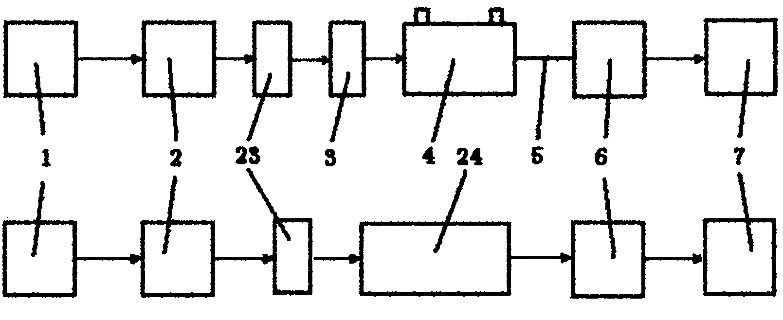
[0041] The use of the hollow-core optical fiber gas-sensing absorption device (4) to replace the open air chamber can improve the light transmission efficiency, increase the detection optical path, and reduce the requirements of the spectral detection method on the light source. We used a comparative experimental device to test the light transmission effect of the hollow-core optical fiber gas-sensing absorption device (4) replacing the open absorption gas chamber.

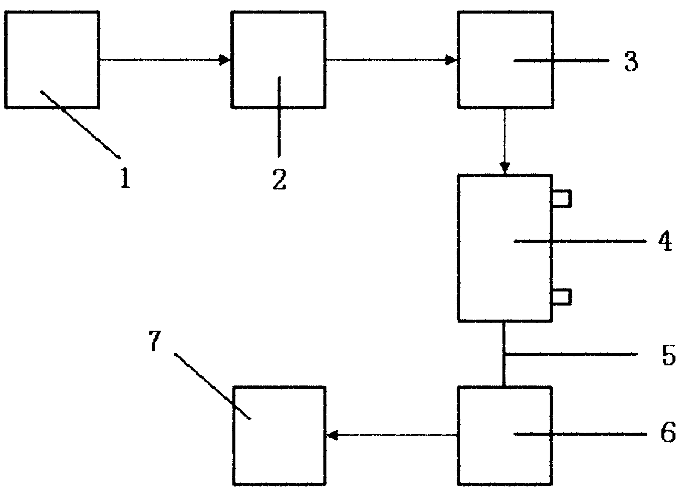
[0042] Experimental device such as image 3 As shown, the optical path structure includes a light source (1), a monochromator (2), an optical chopper (23), a coupler (3), a hollow-core fiber gas-sensitive absorption device (4), a pigtail (5), a photosensitive Component (6), amplifier circuit (7). The contrast optical path includes a light source (1), a monochromator (2), an optical chopper (23), a cou...

Embodiment 3

[0057] Example 3: Application of hollow-core optical fiber gas-sensitive absorption device

[0058] The hollow-core optical fiber gas-sensing absorption device (4) has the characteristics of simple processing, high light source utilization rate and wide transmission range, and the device can directly replace the gas-sensing absorption device in existing instruments to form a new instrument. Various types of gas detection instruments can be constructed conveniently by using the hollow-core optical fiber gas-sensing absorption device (4), light source (1), detector (6), data processing (7) and other systems.

[0059] like figure 1 , 2 As shown, the hollow-core optical fiber gas-sensing absorption device (4), bromine tungsten lamp light source (1), adjustable monochromator (2), coupling lens (3), InGaAs detector (6), host computer system (7) Form a near-infrared detection system. The light emitted by the bromine tungsten light source (1) is incident on the adjustable monochrom...


PUM

PropertyMeasurementUnit
The inside diameter ofaaaaaaaaaa
Outer diameteraaaaaaaaaa
Lengthaaaaaaaaaa

Abstract

The present invention belongs to the technical field of gas-sensitive detection, and relates to a gas-sensitive absorption device based on a hollow optical fibre. By using the hollow property of the hollow optical fibre, when light rays are restrained in the optical fibre for transmission, the detected gas is also capable of passing through the inner part of the hollow optical fibre which can be used as a light transmitting device (an optical waveguide), as well as a light absorption device (an absorption cell). The realizing procedure is that gas flows into the hollow optical fibre via front and back seal heads; optical signals get into the hollow optical fibre via the front seal head, the optical signals spread in the hollow optical fibre and are absorbed by interaction with the detected gas; emergent lights are led into a tail fibre by a taper coupler, and transmitted to a photosensitive detecting element; and the detection of gas content can be realized by light strength change. The device of the present invention has the advantages of wide transmission wavelength range and high transmission efficiency. The device is used for displacing a gas chamber absorption device in a traditional spectrograph, so as to reduce the requirements to light source and mechanical process, and improve the detection performance of the spectrograph.

Description

technical field [0001] The invention belongs to the technical field of gas-sensing detection, and in particular relates to a gas-sensing absorption device based on a hollow optical fiber. The device can replace the sample absorption device in the traditional spectrometer, improve the performance of the absorption device, reduce the requirements of the instrument on the light source, and reduce the processing requirements. Background technique [0002] In the field of gas analysis, the detection of ammonia, hydrocarbons, carbon monoxide and other gases is of great significance in the fields of environmental control, petroleum, chemical industry, mining, building materials, and metallurgy. Among gas analysis instruments, spectrometers are playing an increasingly important role in the field of gas analysis due to their advantages of high precision, good stability, and long service life. The traditional spectrometer gas absorption device adopts a gas chamber device, which requi...

Claims


Application Information

Patent Timeline
IPC IPC(8): G01N21/01
Inventor 王金明索辉蔡昊王贵宝赵纯
Owner JILIN UNIV
Learn More