
Method and system for realizing phase shift in laser interference lithography

A technology of laser interference and positioning system, which is applied in the direction of microlithography exposure equipment, optics, optical components, etc., to achieve the effect of ensuring accuracy

Active Publication Date: 2011-04-13
CHANGCHUN UNIV OF SCI & TECH
View PDF3 Cites 8 Cited by
  • Summary
  • Abstract
  • Description
  • Claims
  • Application Information

AI Technical Summary

Problems solved by technology

[0010] The purpose of the present invention is to overcome the inability of the existing methods and systems to realize pattern positioning in laser interference nanolithography and to propose a method that uses a phase shift positioning system to precisely control the phase shift of interference patterns in laser interference nanolithography

Method used


Image

  • Method and system for realizing phase shift in laser interference lithography
  • Method and system for realizing phase shift in laser interference lithography
  • Method and system for realizing phase shift in laser interference lithography

Examples


Embodiment Construction

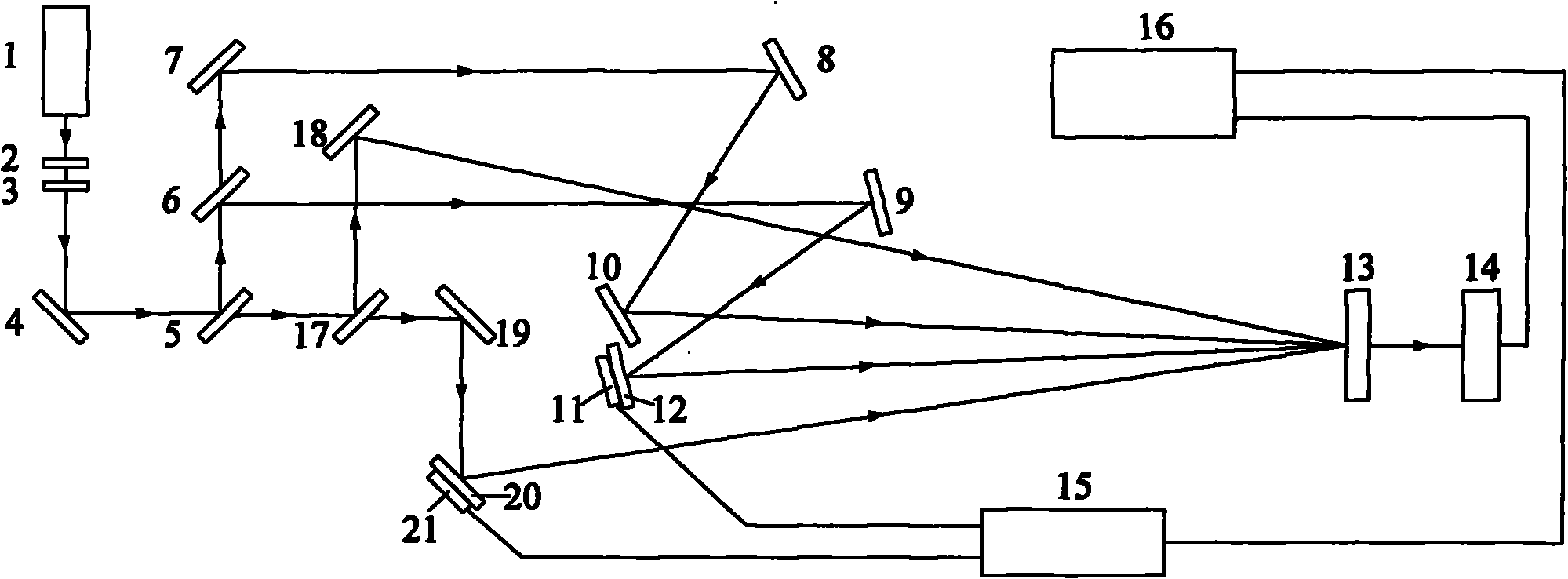
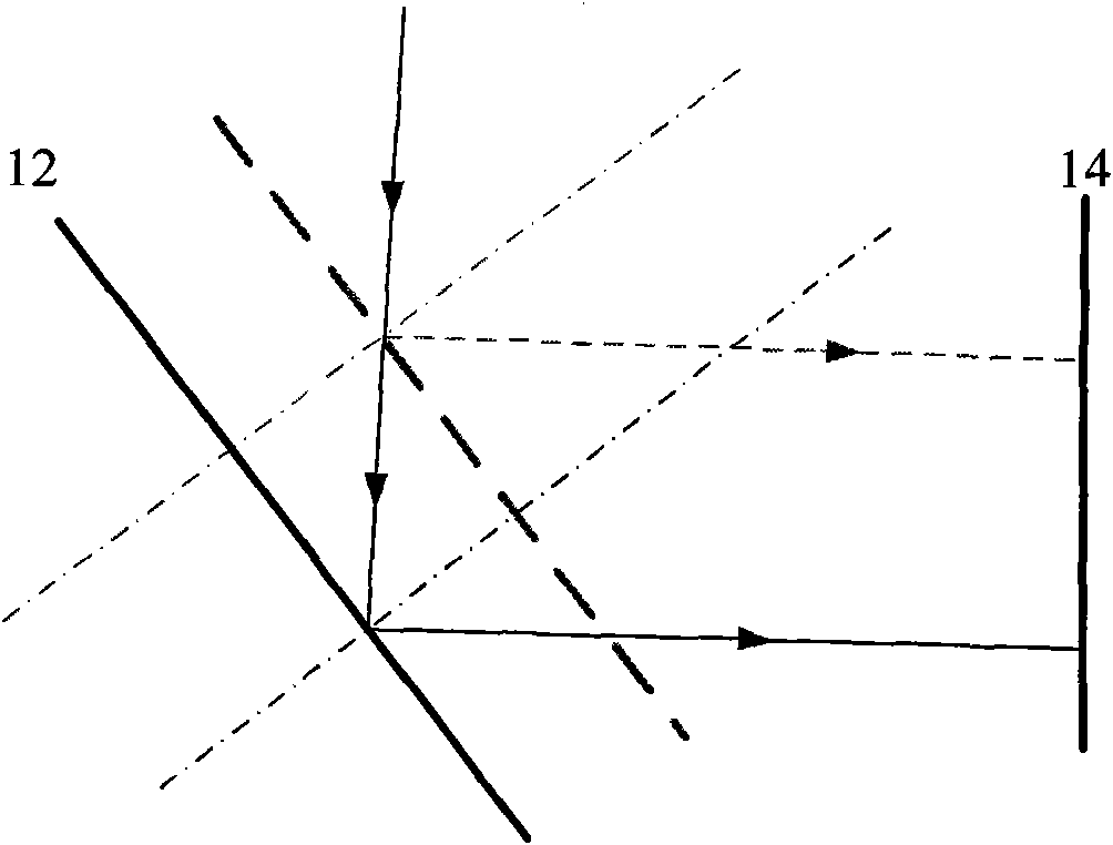
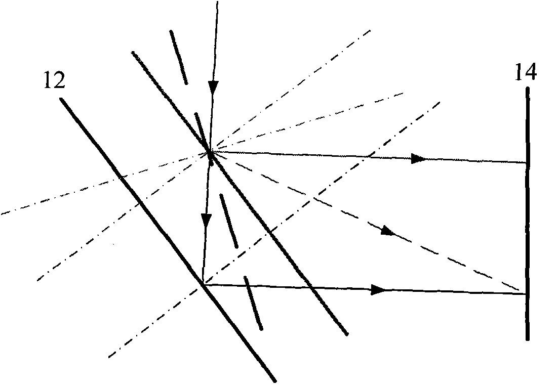
[0028] Such as figure 1 As shown, the four-beam laser interference lithography system adopted in the present invention includes a laser 1 (wavelength 632.8nm), a half-wave plate 2, a polarizer 3, mirrors 4, 7, 8, 9, 10, 12, 18, 19 , 20, beam splitting devices 5, 6, 17, PZT 11, 21 (3 microns / 200 volts), beam expander 13, photocoupler CCD 14, voltage source 15 and computer 16. Among them, PZT 11 is fixed on mirror 12, and PZT 21 is fixed on mirror 20. When voltage source 15 applies different voltages to PZT 11 and PZT 21, PZT 11 and PZT 21 are deformed and move along their axial direction , so that the reflector also moves along the axial direction of PZT 11 and PZT 21, thus changing the optical path and realizing the phase shift and positioning of the interference pattern. The system can detect phase shift through CCD 14 and feedback control phase shift and positioning through computer 16 .

[0029] Such as figure 2 As shown, the optical path can be changed by adjusting the...


PUM


Abstract

The invention discloses a method for shifting a phase in laser interference nano lithography. The method is characterized in that in two-beam or multi-beam laser interference lithography, two or more coherent laser beams are combined for interference, and one or more phase-shift locating systems are controlled to change the optical distance of an optical path and shift and locate the phase of interference graphics. In the method, the phase-shift locating system comprises a voltage source, a displacement driver and a reflector, and different voltages are applied to the displacement driver so that the reflector also moves along the axial direction thereof to shift and locate the phase. The phase-shift locating system can also push an optical wedge in a plane direction perpendicular to incoming light by changing the voltage of the voltage source or control an LCD (Liquid Crystal Display) in the plane direction perpendicular to the incoming light by changing the voltage of the voltage source or control the driver to draw optical fiber to shift the phase of the interference graphics by changing the voltage of the voltage source. The phase-shift method can detect the phase difference of the interference graphics, control the phase shift of the interference graphics by adopting feedback (such as phase locking) and lessen phase shift to more accurately locate the graphics.

Description

technical field [0001] The invention relates to a method for phase shifting in laser interference nanolithography by using a phase shifting positioning system, in particular to a phase shifting positioning system composed of a voltage source, a displacement driver and a reflection mirror with a simple structure. technical background [0002] The principle of the laser interference nanolithography system is to use the energy distribution of the periodic or quasi-periodic interference pattern generated by the interference of two or more laser beams and the interaction of the lithographic material to manufacture surface micro-nano structures. It is a lithographic technique that does not require mask-based manufacturing cycles or quasi-periodic patterns. The interference pattern can be a fringe pattern produced by the interference of two beams or a lattice pattern produced by the interference of multiple beams. This technique does not require expensive optical projection system...

Claims


Application Information

Patent Timeline
Patent Type & Authority Applications(China)
IPC IPC(8): G02B26/06G03F7/20
Inventor 张薇王作斌徐佳刘兰娇侯煜潘海艳宋浩刘洋翁占坤宋正勋胡贞
Owner CHANGCHUN UNIV OF SCI & TECH
Learn More