
Quick-braking engine brake device

An engine braking and fast technology, applied in the direction of engine components, machines/engines, valve devices, etc., can solve the problems of large inertia, slow response, increased engine height and manufacturing costs of the braking system, and achieve cost reduction and reduction Requirements, effects of volume and weight reduction

Inactive Publication Date: 2011-04-06
SHANGHAI UNIVERSOON AUTOPARTS CO LTD
View PDF1 Cites 2 Cited by
  • Summary
  • Abstract
  • Description
  • Claims
  • Application Information

AI Technical Summary

Problems solved by technology

[0006] The purpose of the present invention is to provide a fast braking engine braking device, which will solve the problem that the overhead mode of the engine braking system in the prior art increases the height of the engine and the The technical problem of manufacturing cost, at the same time, it is necessary to solve the technical problem of large inertia and slow response of the braking system existing in the hydraulically driven engine brake

Method used


Image

  • Quick-braking engine brake device
  • Quick-braking engine brake device
  • Quick-braking engine brake device

Examples


Embodiment 1

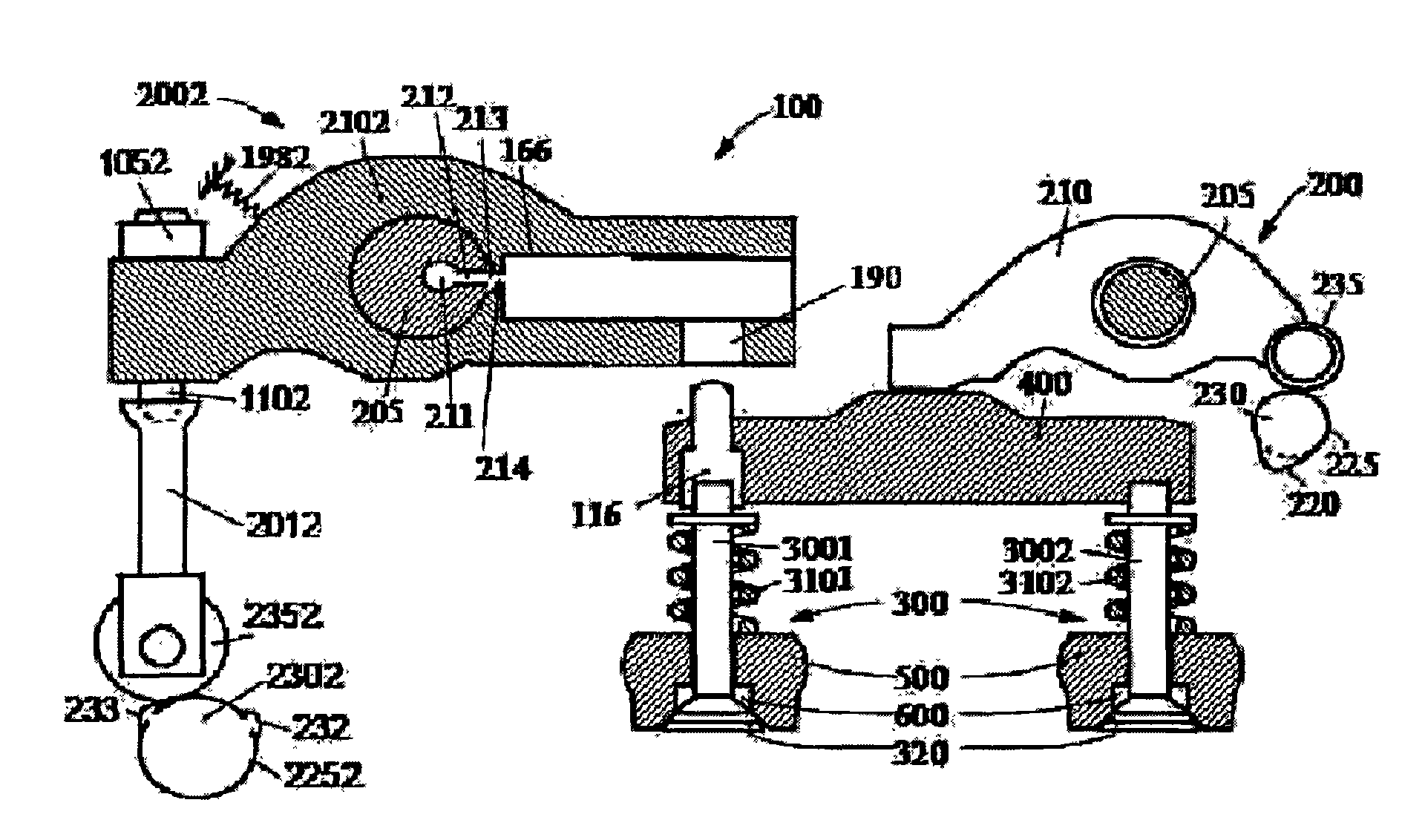
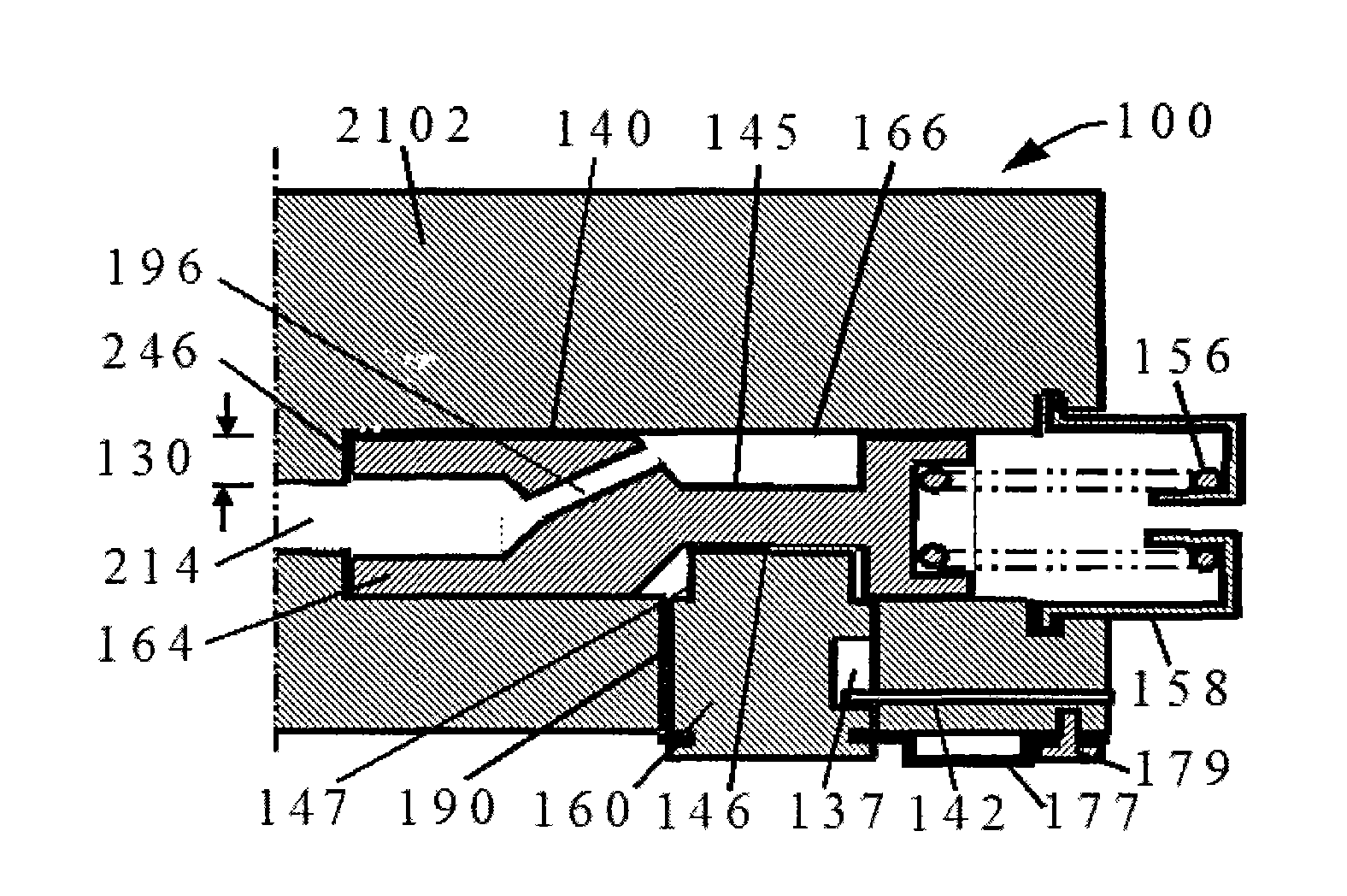
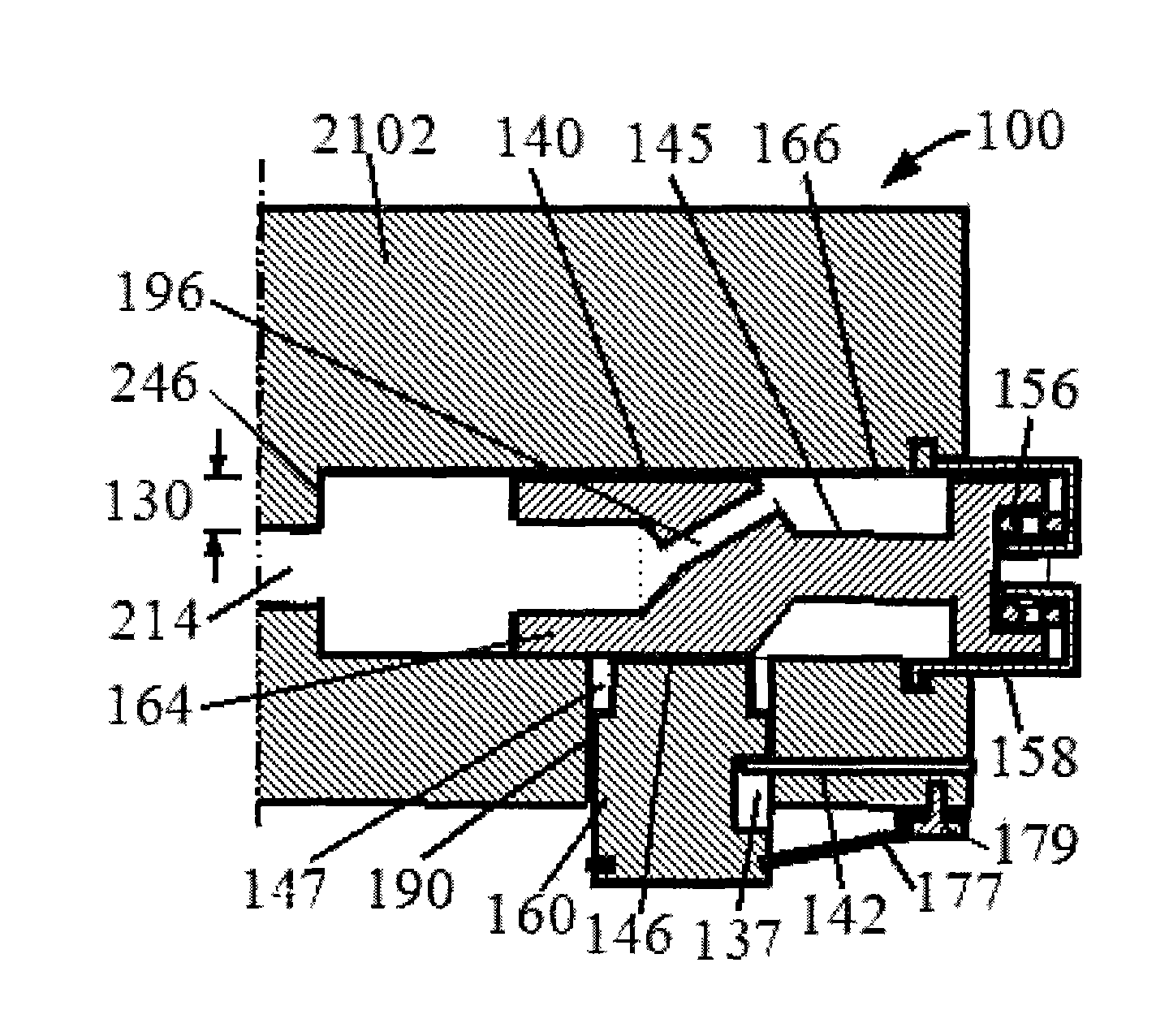
[0026] like figure 1 , figure 2 , image 3 , Figure 4 and Figure 5As shown, a fast braking engine braking device 100 of the present invention is composed of an exhaust valve control mechanism 2002, wherein the exhaust valve control mechanism 2002 is composed of a driving force input cam 2302, a cam follower 2352 , a push rod 2012, a rocker arm 2102 and a rocker shaft 205, the middle part of the rocker arm 2102 is set on the rocker shaft 205, one end of the push rod 2012 is connected with one end of the rocker arm 2102, and the Cam follower 2352 is arranged in the other end of push rod 2012, and described driving force input cam 2302 is arranged outside cam follower 2352, and the rotation circle of protruding part 232,233 in the driving force input cam 2302 and cam follower 2352 The outer circumference of the rocker arm 2102 is provided with a bias return spring 1982, the rocker arm 2102 is provided with a liquid channel 214, and the other end of the rocker arm 2102 is p...


PUM


Abstract

The invention discloses a quick-braking engine brake device, which consists of an exhaust valve control mechanism, wherein the exhaust valve control mechanism consists of a driving force input cam, a cam driven wheel, a push rod, a rocker arm and a rocker arm shaft; one end of the push rod is connected with one end of the rocker arm; the cam driven wheel is arranged on the other end of the push rod; the driving force input cam is arranged outside the cam driven wheel; the other end of the rocker arm is provided with a horizontal driving piston and a vertical braking piston cylinder; a circular groove is formed on the middle part of the driving piston; a lateral side of the circular groove and the lateral surface, on the left of the circular groove, of the driving piston serve as a non-working face and a working face to contact the upper end face of the braking piston cylinder in a pressed way respectively; and a valve rod connector of an air exhaust valve is arranged below the braking piston cylinder. The driving force input cam transmits the power of an engine to the rocker arm periodically, the gap between the rocker arm and the valve rod connector of the air exhaust valve is controlled by an electromagnetic valve to realize switching between braking and normal working two states, so that the volume and weight of the brake are reduced, and high oil pressure and leakage, deformation and load fluctuation caused by the high oil pressure are avoided.

Description

Technical field: [0001] The invention relates to the mechanical field, in particular to an engine braking device, in particular to a fast-braking engine braking device. Background technique: [0002] In the prior art, the method of using the internal combustion engine as a braking means is well known, and only the engine needs to be temporarily converted into a compressor. This conversion cuts off the fuel and opens the exhaust valve at or near the end of the engine piston compression stroke, allowing the compressed gas (air during braking) to be released. The energy absorbed by the engine during the compression stroke cannot be used The subsequent expansion stroke returns to the engine piston, but is dissipated through the engine's exhaust and cooling system. The end result is effective engine braking that slows the vehicle. [0003] A precedent for an engine brake is disclosed in US Patent No. 3,220,392 to Cummins, according to which an engine braking system has been man...

Claims


Application Information

Patent Timeline
Patent Type & Authority Applications(China)
IPC IPC(8): F01L13/06
Inventor 杨洲王琳
Owner SHANGHAI UNIVERSOON AUTOPARTS CO LTD
Learn More