
Automatic spot welding equipment

An automatic spot welding and equipment technology, applied in welding equipment, resistance welding equipment, metal processing equipment and other directions, can solve the problems of high labor intensity, difficult product welding quality, low production efficiency, etc., to improve quality and production efficiency, improve The effect of market competitiveness and production cost saving

Active Publication Date: 2011-03-30
GUANGDONG LYRIC ROBOT INTELLIGENT AUTOMATION CO LTD
View PDF5 Cites 62 Cited by
  • Summary
  • Abstract
  • Description
  • Claims
  • Application Information

AI Technical Summary

Problems solved by technology

[0003] At present, the welding of batteries and soldering tabs mainly relies on manual welding. However, manual welding largely depends on manual technical proficiency, and it is impossible to guarantee the position of each welding. Similarly, the scrap rate is high, it is difficult to ensure the welding quality of the product, the labor intensity is also high, and the production efficiency is difficult to improve. The manual welding method is far from meeting the needs of production development; Feeding with the solder sheet, manual feeding, and low production efficiency; in addition, the battery performance needs to be tested during the welding process, and manual testing is prone to missed and false detections, resulting in defective products

Method used


Image

  • Automatic spot welding equipment
  • Automatic spot welding equipment
  • Automatic spot welding equipment

Examples


Embodiment Construction

[0030] For the convenience of those skilled in the art to understand, the following In conjunction with specific embodiment and accompanying drawing to this

[0031] Inventive structure principle is described in further detail:

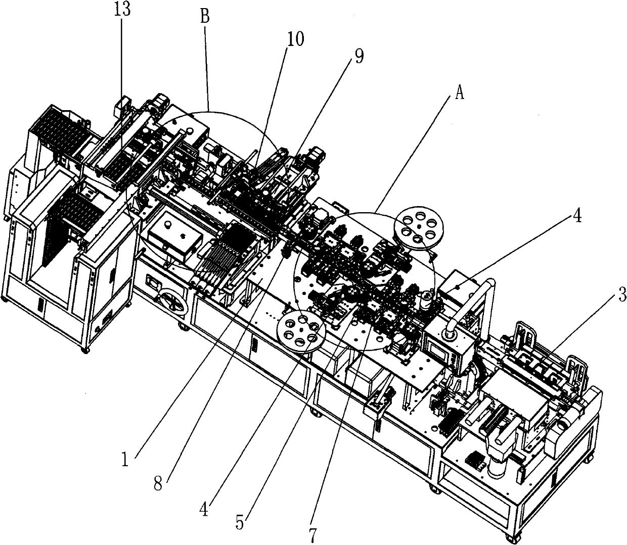
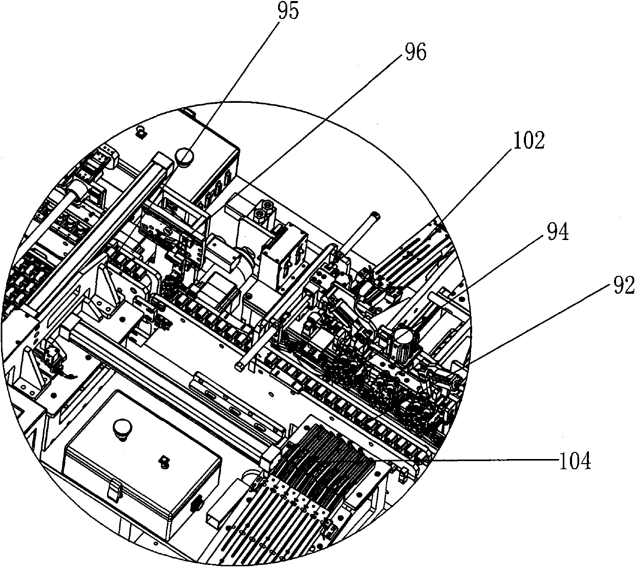
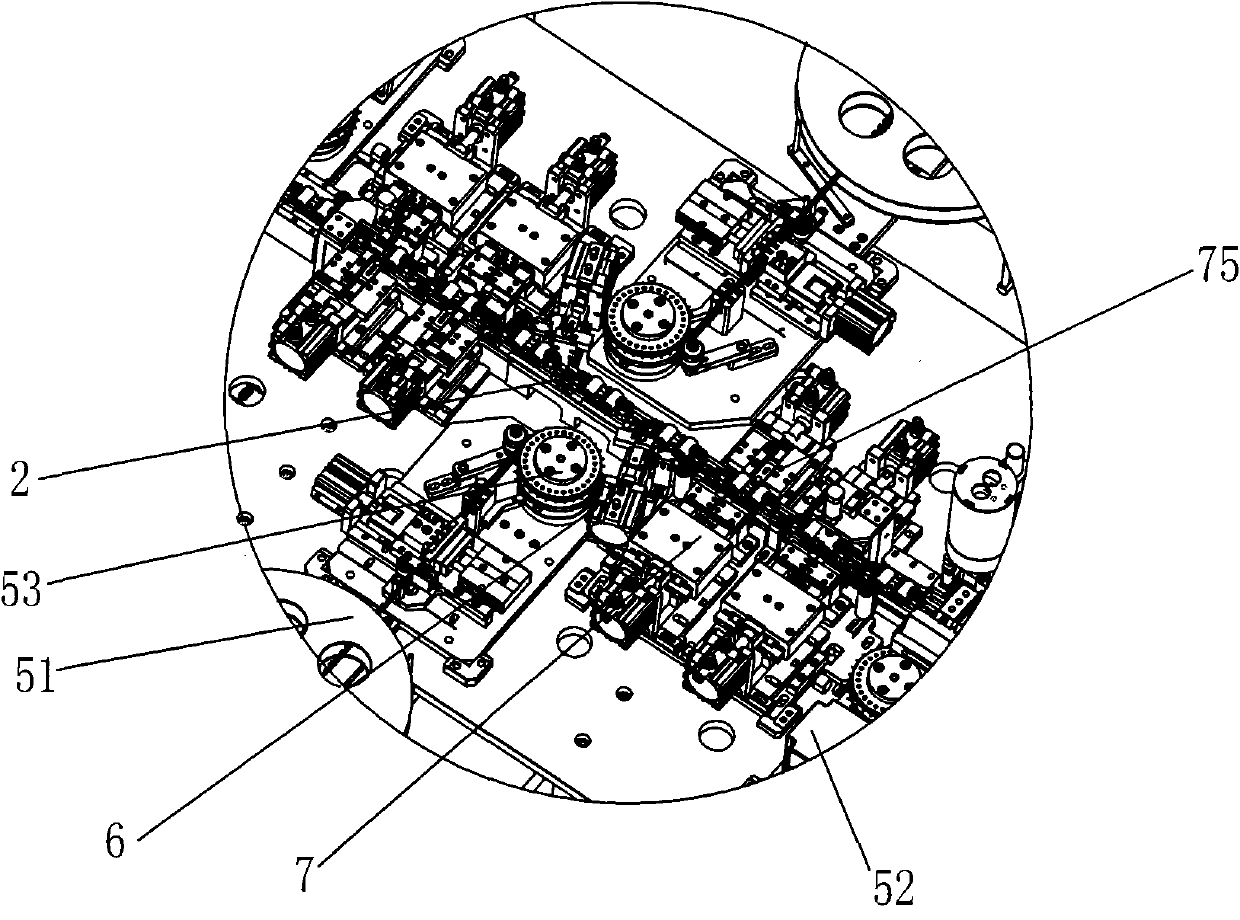
[0032] as attached Figure 1-13 , an automatic spot welding equipment, including a frame and a workbench 1 arranged on the frame, on the workbench 1, a battery feeding mechanism 3, a transfer mechanism 2, a battery label alignment mechanism 4, and a steel strip feeding mechanism are arranged in sequence 5. Solder sheet cutting mechanism 6, welding mechanism 7, reflective optical fiber detection mechanism 8, good product unloading mechanism 9, defective product recovery mechanism 10, battery feeding mechanism 3 and steel belt feeding mechanism 4 respectively The battery 11 and the steel strip 12 are sent into the welding station, the steel strip 12 is connected with a solder piece 121, the transfer mechanism 2 carries and transfers the battery 11, ...


PUM


Abstract

The invention relates to automatic spot welding equipment which comprises a stand and a workbench arranged on the stand, wherein the workbench is provided with a battery feed mechanism, a steel band feed mechanism, a transfer mechanism, a welding tab cut-off mechanism, a welding mechanism and a good product blanking mechanism, wherein the battery feed mechanism and the steel band feed mechanism are respectively used for feeding a battery and a steel band connected with a welding tab into a welding station; the transfer mechanism is used for bearing and transferring the battery; the welding tab cut-off mechanism is used for cutting off the welding tab on the steel band; the welding mechanism is used for welding the welding tab to the anode end and the cathode end of the battery; the transfer mechanism is provided with a battery clamping seat used for clamping the battery, and an elastic piece inwards pressing the battery is arranged on the battery clamping seat; and the mechanisms are connected with a master control circuit. In the invention, the structural design of the equipment is reasonable, and the automatic feeding, the welding and the property detecting of the battery and the steel band are realized by adopting electrical control, thus the equipment has the advantages of high feed speed, high welding precision and good welded product quality, improves the quality and the production efficiency of the welded product, reduces the labor intensity of workers, saves the production cost and is particularly suitable for producing batteries welded with welding tabs in batches, thereby improving market competitive force of enterprises.

Description

technical field [0001] The invention belongs to the technical field of spot welding, and specifically refers to an integrated device capable of realizing automatic feeding, welding and performance testing of batteries and steel strips. Background technique [0002] With the development of science and technology, batteries are used more and more widely, and consumers have higher and higher requirements for their quality. In the production and manufacture of batteries, it is necessary to weld solder tabs on both ends of the positive and negative electrodes of the battery, so as to meet the processing and use requirements of battery products. [0003] At present, the welding of batteries and soldering tabs mainly relies on manual welding. However, manual welding largely depends on manual technical proficiency, and it is impossible to guarantee the position of each welding. Similarly, the scrap rate is high, it is difficult to ensure the welding quality of the product, the lab...

Claims


Application Information

Patent Timeline
Patent Type & Authority Applications(China)
IPC IPC(8): B23K11/11B23K11/36
Inventor 周俊雄周俊豪周俊杰
Owner GUANGDONG LYRIC ROBOT INTELLIGENT AUTOMATION CO LTD
Learn More