
mim capacitor and its manufacturing method

A manufacturing method and technology of capacitors, which are applied in semiconductor/solid-state device manufacturing, circuits, electrical components, etc., can solve the problems of large differences in molecular structure, poor connection force, peeling and scattering of upper plate metal 3, etc.

Inactive Publication Date: 2011-11-30
SEMICON MFG INT (SHANGHAI) CORP
View PDF0 Cites 0 Cited by
  • Summary
  • Abstract
  • Description
  • Claims
  • Application Information

AI Technical Summary

Problems solved by technology

However, because the molecular structure difference between the dielectric layer 2 and the upper plate metal 3 is relatively large, and the connection force between the two is poor, when the upper plate metal 3 is formed on the dielectric layer 2, it will cause damage to the surface of the dielectric layer 2. Dislocation, especially between the upper plate metal 3 and the dielectric layer 2 on the protruding side of the substrate 10 will generate a large dislocation force, causing the upper plate metal 3 to peel off from the dielectric layer 2 and scatter to the The entire wafer may lead to the scrapping of the entire wafer, which will cause a large loss

Method used


Image

  • mim capacitor and its manufacturing method
  • mim capacitor and its manufacturing method
  • mim capacitor and its manufacturing method

Examples


Embodiment Construction

[0017] In order to make the above objects, features and advantages of the present invention more comprehensible, specific implementations of the present invention will be described in detail below in conjunction with the accompanying drawings.

[0018] In the following description, numerous specific details are set forth in order to provide a thorough understanding of the present invention. However, the present invention can be implemented in many other ways different from those described here, and those skilled in the art can make similar extensions without violating the connotation of the present invention, so the present invention is not limited by the specific implementations disclosed below.

[0019] Secondly, the present invention is described in detail using schematic diagrams. When describing the embodiments of the present invention in detail, for the convenience of explanation, the cross-sectional view showing the device structure will not be partially enlarged accordi...


PUM

PropertyMeasurementUnit
thicknessaaaaaaaaaa
thicknessaaaaaaaaaa

Abstract

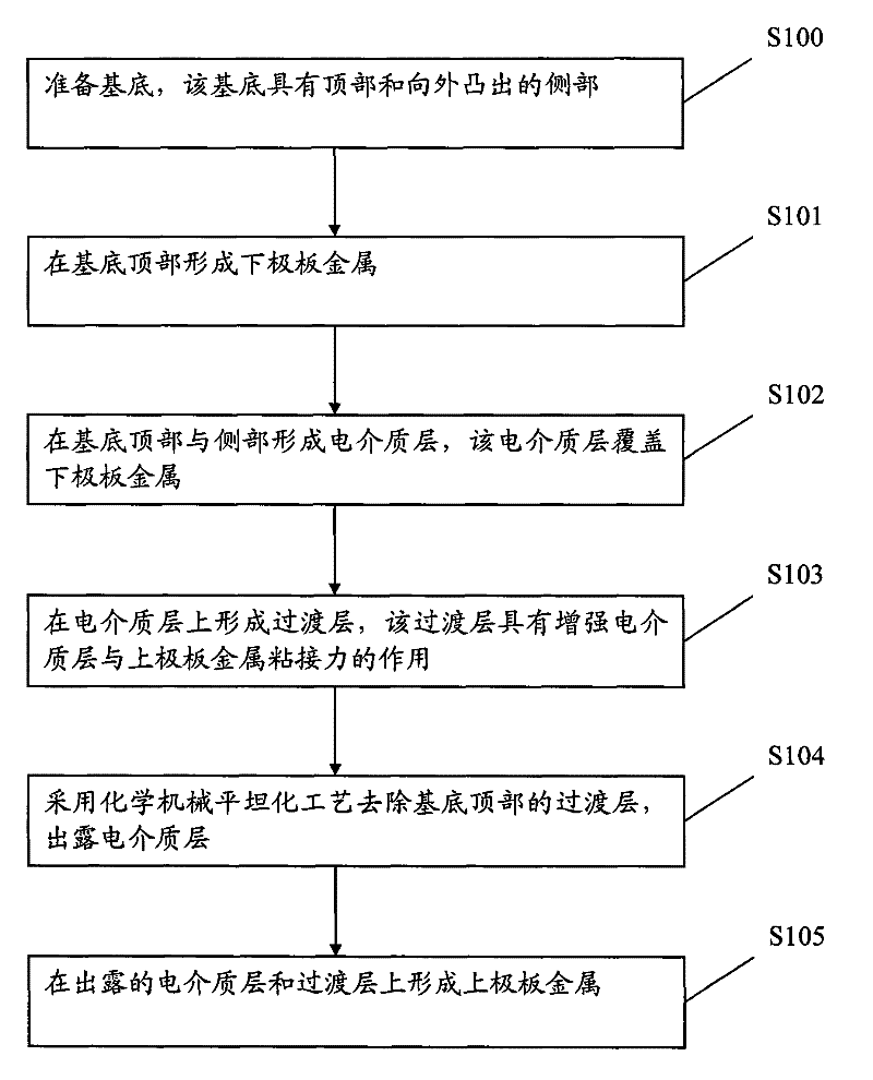
The invention relates to a manufacturing method of a MIM capacitor, comprising the following steps: preparing a substrate, the substrate has a top and outwardly protruding side portions; forming a lower plate metal on the top of the substrate; forming a dielectric layer on the top and side portions of the substrate, The dielectric layer covers the metal of the lower plate; a transition layer is formed on the dielectric layer, and the transition layer has the effect of enhancing the adhesion between the dielectric layer and the metal of the upper plate; the transition layer on the top of the substrate is removed by chemical mechanical planarization process, and the exposed The dielectric layer retains the transition layer on the side of the base; the upper plate metal is formed on the exposed dielectric layer and the transition layer. Due to the implementation of the above technical scheme, the connection between the metal on the upper plate and the dielectric layer is firm, the metal on the upper plate will not peel off, and the yield rate of the MIM capacitor can be improved; and, due to the adoption of a special process, the properties of the capacitor are not Affected.

Description

technical field [0001] The present invention relates to a metal-insulator-metal (metal-insulator-metal, hereinafter referred to as MIM) capacitor and a manufacturing method thereof. Background technique [0002] Capacitive components are often used as electronic passive devices in integrated circuits such as radio frequency ICs and monolithic microwave ICs. Common capacitor structures include metal oxide semiconductor (MOS) capacitors, PN junction capacitors, and MIM capacitors. Among them, MIM capacitors provide better electrical characteristics than MOS capacitors and PN junction capacitors in some special applications. This is because MOS capacitors and PN junction capacitors are limited by their own structures, and the electrodes are prone to generate hole layers during operation. , causing its frequency characteristics to degrade. The MIM capacitor can provide better frequency and temperature-related characteristics. In addition, in semiconductor manufacturing, MIM c...

Claims


Application Information

Patent Timeline
Patent Type & Authority Patents(China)
IPC IPC(8): H01L29/92H01L21/02
Inventor 叶菁王奇峰
Owner SEMICON MFG INT (SHANGHAI) CORP
Learn More