Radial-radial magnetic field modulation type brush-less composite structure motor
A composite structure, radial magnetic field technology, applied in the magnetic circuit shape/style/structure, synchronous motors with static armatures and rotating magnets, electrical components, etc. problems, to achieve the effect of reducing exhaust emissions, small size, wide range and stable speed regulation
- Summary
- Abstract
- Description
- Claims
- Application Information
AI Technical Summary
Problems solved by technology
Method used
Image
Examples
specific Embodiment approach 1
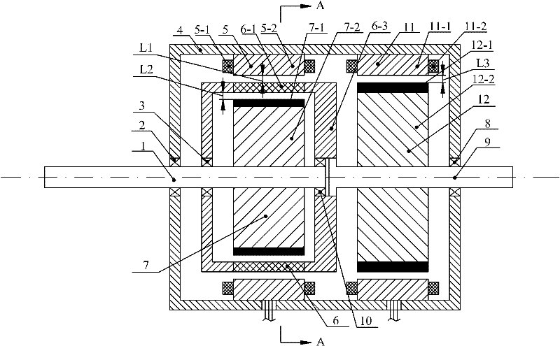
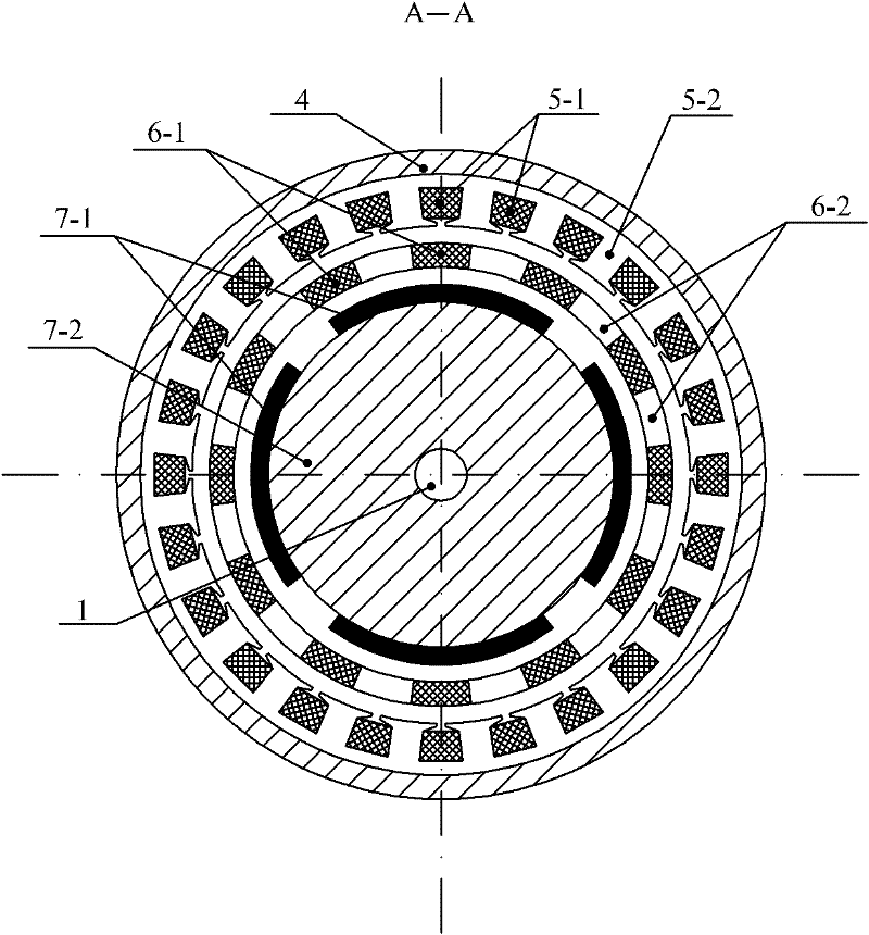
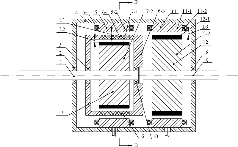
[0037] Specific implementation mode one: the following combination Figure 1 to Figure 21 To illustrate this embodiment, the motor of this embodiment is provided with a radial double-rotor motor and a radial torque adjustment motor in parallel in the housing 4, and the radial double-rotor motor includes a first stator 5, a modulation ring rotor 6, The first permanent magnet rotor 7, the permanent magnet rotor output shaft 1 and the modulation ring rotor output shaft 9, the radial torque regulating motor includes the second stator 11 and the second permanent magnet rotor 12, and the modulation ring rotor output shaft 9 simultaneously serves as The rotor shaft of the radial torque adjustment motor,
[0038] The second stator 11 of the radial torque regulating motor is fixed on the inner side wall of the housing 4, and the second permanent magnet rotor 12 is fixed on the modulation ring rotor output shaft 9. The second stator 11 and the second permanent magnet rotor 12 There is ...
specific Embodiment approach 2
[0077] Specific implementation mode two: the following combination figure 1 with figure 2 Describe this embodiment, the difference between this embodiment and Embodiment 1 is that the first permanent magnet unit 7-1 is arranged on the outer circular surface of the first permanent magnet rotor core 7-2, and the first permanent magnet unit 7-1 1 Magnetize radially or parallelly magnetize radially, other structures and connection methods are the same as Embodiment 1.
specific Embodiment approach 3
[0078] Specific implementation mode three: the following combination image 3 with Figure 4 Describe this embodiment, the difference between this embodiment and Embodiment 1 is that the first permanent magnet unit 7-1 is embedded in the outer circular surface of the first permanent magnet rotor core 7-2, and the first permanent magnet unit 7 -1 Magnetize radially or parallelly magnetize radially, other structures and connections are the same as those in Embodiment 1.
PUM
 Abstract
Description
Claims
Application Information
 - R&D
- Intellectual Property
- Life Sciences
- Materials
- Tech Scout
- Unparalleled Data Quality
- Higher Quality Content
- 60% Fewer Hallucinations
Browse by: Latest US Patents, China's latest patents, Technical Efficacy Thesaurus, Application Domain, Technology Topic, Popular Technical Reports.
© 2025 PatSnap. All rights reserved.Legal|Privacy policy|Modern Slavery Act Transparency Statement|Sitemap|About US| Contact US: help@patsnap.com


