
Internal combustion engine

An internal combustion engine and engine technology, applied in the power field, can solve the problems of frustration, low work efficiency, limited efficiency, etc., and achieve the effects of reducing environmental damage, reducing exhaust emissions, and facilitating power performance.

Inactive Publication Date: 2007-04-18
张凡胜
View PDF0 Cites 1 Cited by
  • Summary
  • Abstract
  • Description
  • Claims
  • Application Information

AI Technical Summary

Problems solved by technology

However, due to some basic characteristics of existing internal combustion engines, further improvements in their efficiency have been limited
[0003] For example, the existing internal combustion engine structure adopts mechanical transmission, and its self-weight is too large, resulting in serious self-loss and low work efficiency, and it is difficult to further improve the combustion efficiency of the internal combustion engine
And when the internal combustion engine is used as power, the kinetic energy is wasted in the braking process, and a large amount of pollution is also produced
In addition, the existing internal combustion engines still have problems such as incompatibility of oil products and frustration when changing gears.
[0004] Due to the above reasons, the existing internal combustion engine technology cannot achieve higher energy conversion efficiency. Therefore, it is necessary to find another way and adopt a new design idea to realize the conversion between fuel work and mechanical operation, so as to further improve efficiency.

Method used


Image

  • Internal combustion engine
  • Internal combustion engine
  • Internal combustion engine

Examples


Embodiment Construction

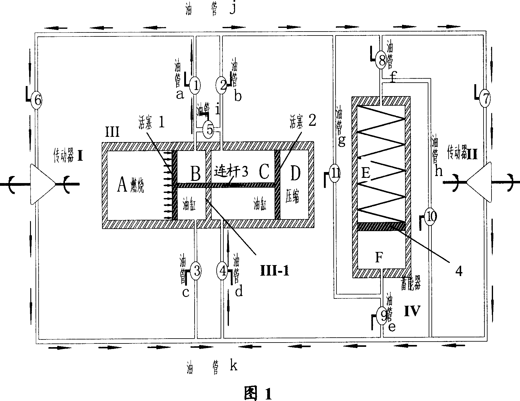
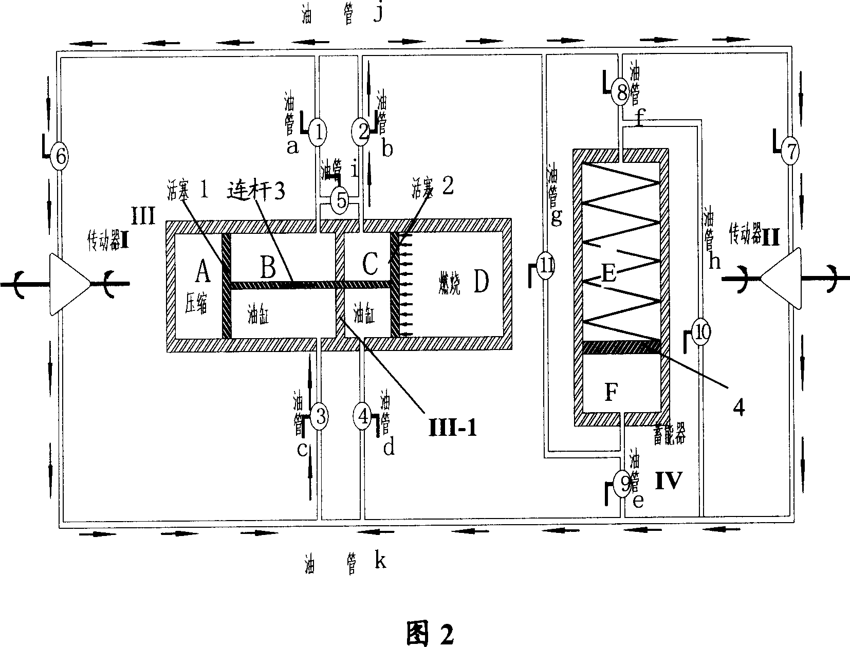
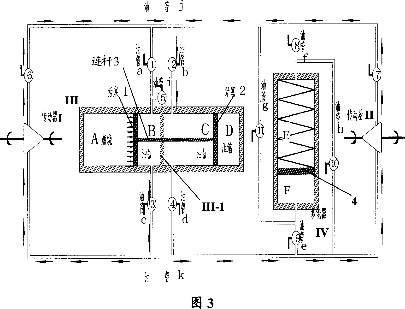
[0039] Please refer to FIG. 1 , which is a schematic diagram of the first embodiment of the present invention. The figure shows the basic structure of the engine. The normal running of the engine includes two working states, and Fig. 1 shows the first state of the engine in the normal running state.

[0040] As shown in FIG. 1 , the engine includes a transmission I and a transmission II, and the above-mentioned transmissions are connected to oil pipes. When the hydraulic oil in the oil pipe flows through the transmission, the blades in the transmission rotate under the impact force of the hydraulic oil, thus providing kinetic energy to the outside.

[0041]The heart of the engine is the combustor / cylinder chamber III. Said chamber III is divided into two equal parts by a dividing wall III-1. Wherein, the left cavity of the cavity III is divided into a combustion chamber A and an oil cylinder B by the piston 1 . The piston 1 has a good seal, so that the combustion chamber A...


PUM


Abstract

This invention discloses a kind of internal combustion engine, including : driver, the driver is connected between fluid power oil circuit, when the fluid power oil flows across the driver, the said moving components rotates in the effect of the fluid power oil , export power; oil cylinder , the oil cylinder links with the fluid power oil circuit of the both ends of the said driver with two vitta ,the driver has oil cylinder piston, the oil cylinder piston can move along the oil cylinder wall to extrude the fluid power oil in the oil cylinder, provide the fluid power pressure to the fluid power oil in the oil circuit ; firebox, the firebox provides enclosed space to the fuel burning, meanwhile the volume of gas in the firebox inflates to promote the oil cylinder piston to move. The internal combustion engine in the invention uses fluid power type to achieve energy transfer. When the combustion work transfers into output mechanical energy, the engine need not use the middle mechanical link, therefore, comparing with the existing fuel engine, the fuel engine has significant advantage.

Description

technical field [0001] The invention relates to power technology, in particular to an internal combustion engine. Background technique [0002] An internal combustion engine (abbreviated as an internal combustion engine) is a widely used source of power, especially for various motor vehicles. Existing internal combustion engines use fuel combustion as power, and output power through mechanical transmission. This internal combustion engine form has been practical for many years, and its technology is very mature. At present, various methods have been adopted to improve the combustion efficiency of internal combustion engines and reduce emissions. However, due to some fundamental characteristics of existing internal combustion engines, further improvements in their efficiency have been limited. [0003] For example, the existing internal-combustion engine structure adopts mechanical transmission, and its self-weight is too large, resulting in serious self-loss and low work ...

Claims


Application Information

Patent Timeline
Patent Type & Authority Applications(China)
IPC IPC(8): F02B71/04
Inventor 张凡胜张圣卿张纪元
Owner 张凡胜
Learn More