
Electrical-hydraulic control device of anti-falling constraining device

A restraint device, electro-hydraulic control technology, applied in the direction of fluid pressure actuation device, servo motor, mechanical equipment, etc., can solve the problems of poor blood circulation of local skin, difficult control of restraint force, physical damage of restrained objects, etc. Light weight, ensure safety and work stability, avoid the effect of physical damage

Inactive Publication Date: 2014-12-10
YANSHAN UNIV
View PDF6 Cites 1 Cited by
  • Summary
  • Abstract
  • Description
  • Claims
  • Application Information

AI Technical Summary

Problems solved by technology

The size of the restraint force of this type of restraint device is not easy to control, the reliability is not high, it consumes manpower, and it is easy to cause physical damage to the restrained object. Tight and lead to poor blood circulation in the local skin, resulting in damage

Method used


Image

  • Electrical-hydraulic control device of anti-falling constraining device
  • Electrical-hydraulic control device of anti-falling constraining device
  • Electrical-hydraulic control device of anti-falling constraining device

Examples


Embodiment 1

[0035] Embodiment 1: A system implementation mode using an electro-hydraulic control system.

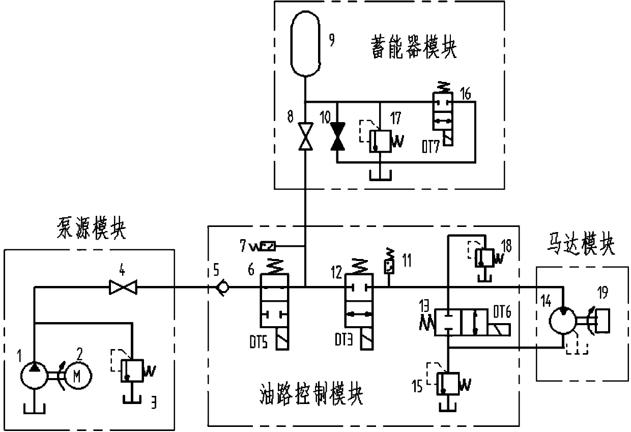
[0036] An electro-hydraulic control device for an anti-off restraint device, such as figure 1 As shown, including pump source module, oil circuit control module, accumulator module and motor module;

[0037] Such as figure 2 As shown: the pump source module includes a hydraulic pump 1, a motor 2, a first relief valve 3 and a first stop valve 4, the hydraulic pump 1 and the motor 2 are connected through a coupling, the inlet of the hydraulic pump 1 is connected to the oil tank, Its outlet is connected to the first relief valve 3, and the oil return port of the first relief valve 3 is connected to the oil tank. At the same time, the outlet of the hydraulic pump 1 is connected to the first stop valve 4, and the first stop valve 4 is connected to the one-way valve of the oil circuit control module. valve 5;

[0038] The oil circuit control module includes a check valve 5, a first ele...

Embodiment 2

[0046] Embodiment 2: A system implementation mode using a hydraulic control system.

[0047] A hydraulic control device for an anti-off restraint device, such as figure 1 As shown, including pump source module, oil circuit control module, accumulator module, motor module;

[0048] The pump source module and the motor module are the same as those in the hydraulic system of the electro-hydraulic control system.

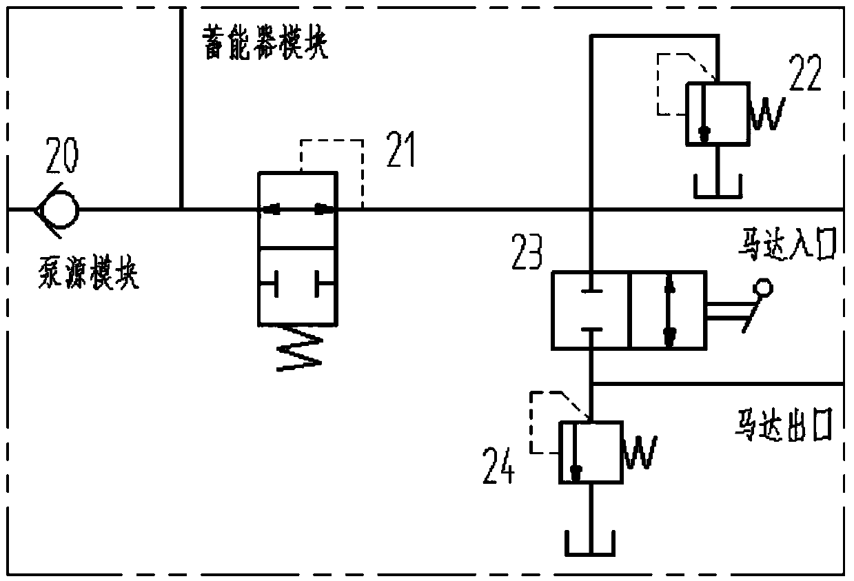
[0049] Such as image 3 As shown, the oil circuit control module includes a one-way valve 20, a hydraulic reversing valve 21, a manual reversing valve 23, a second relief valve 24 and a safety valve 22, and one end of the one-way valve 20 is connected to the first valve of the pump source module. A cut-off valve 4, the other end of which is connected to the hydraulic reversing valve 21, and the hydraulic oil is divided into three routes after passing through the hydraulic reversing valve 21, wherein: one route returns to the oil tank after passing through the safety v...


PUM


Abstract

The invention discloses an electrical-hydraulic control device of an anti-falling constraining device. The electrical-hydraulic control device comprises a pump source module, an oil path control module, an energy accumulator module and a motor module, the pump source module comprises a hydraulic pump, a motor, a first overflow valve and a first stop valve, the oil path control module comprises a check valve, a first electromagnetic directional valve, a second electromagnetic directional valve, a third electromagnetic directional valve, a second overflow valve, a safety valve, a first pressure relay and a second pressure relay, the energy accumulator module comprises an energy accumulator, a second stop valve, a third stop valve, a third overflow valve and a fourth electromagnetic directional valve, and the motor module comprises a motor and a constraining belt fixing device. The electrical-hydraulic control device is high in automation degree and can be remotely controlled, the output torque can be precisely adjusted, the adjusting range is large, an object is constrained, and meanwhile the object cannot be damaged. The electrical-hydraulic control mode can be adopted, the hydraulic drive control mode can also be adopted, and the different requirements of a user for working with the high automation degree or under the low-cost and bad working condition can be met.

Description

technical field [0001] The invention relates to a control device, in particular to an electro-hydraulic control device of an anti-escape restraint device. Background technique [0002] In the field of restraint for mental patients, criminals, and goods with anti-damage requirements, the existing restraint devices are all manually operated, relying on rigid locking or flexible locking of mechanical structures, such as binding restrained objects with restraint belts. The size of the restraint force of this type of restraint device is not easy to control, the reliability is not high, it consumes manpower, and it is easy to cause physical damage to the restrained object. Tight and lead to poor blood circulation in the local skin, resulting in damage. Contents of the invention [0003] The purpose of the present invention is to overcome the deficiencies in the prior art and provide a control device for an electromechanical-hydraulic integrated restraint device with adjustable ...

Claims


Application Information

Patent Timeline
Patent Type & Authority Applications(China)
IPC IPC(8): F15B1/02F15B11/028
Inventor 郭锐赵静一张毅
Owner YANSHAN UNIV
Learn More