Pressure compensation device of grinding machine and using method of pressure compensation device

A technology of pressure compensation and grinding machine, which is applied in the direction of grinding driving device, grinding machine parts, grinding workpiece support, etc., which can solve the problems of labor loss, multi-view angle, consumption, etc., and achieve the advantages of simple operation and reduced offset Effect

Active Publication Date: 2021-04-27
广州科源数控科技有限公司
View PDF5 Cites 1 Cited by
  • Summary
  • Abstract
  • Description
  • Claims
  • Application Information

AI Technical Summary

Problems solved by technology

In this process, although the surface of the mold parts can be polished and polished, according to the polishing and polishing process, the polishing and polishing is often done layer by layer with a small amount of polishing. Therefore, when polishing and polishing manually, the effect of surface polishing will be observed after polishing to a certain depth. , and whether the dimensional change is within the qualified range, so it will consume more viewing angles and cause labor loss

Method used


Image

  • Pressure compensation device of grinding machine and using method of pressure compensation device
  • Pressure compensation device of grinding machine and using method of pressure compensation device
  • Pressure compensation device of grinding machine and using method of pressure compensation device

Examples


Embodiment Construction

[0030] The present invention will be further described in detail below in conjunction with the accompanying drawings and specific embodiments. Terms such as "upper", "inner", "middle", "left", "right" and "one" quoted in this specification are only for the convenience of description, and are not used to limit the scope of the present invention. The scope of implementation and the change or adjustment of its relative relationship shall also be regarded as the scope of implementation of the present invention without substantive changes in technical content.

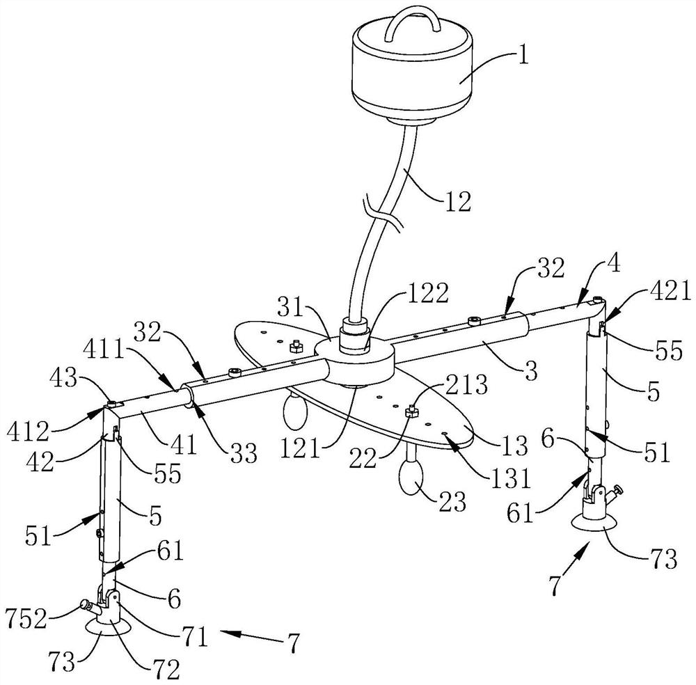
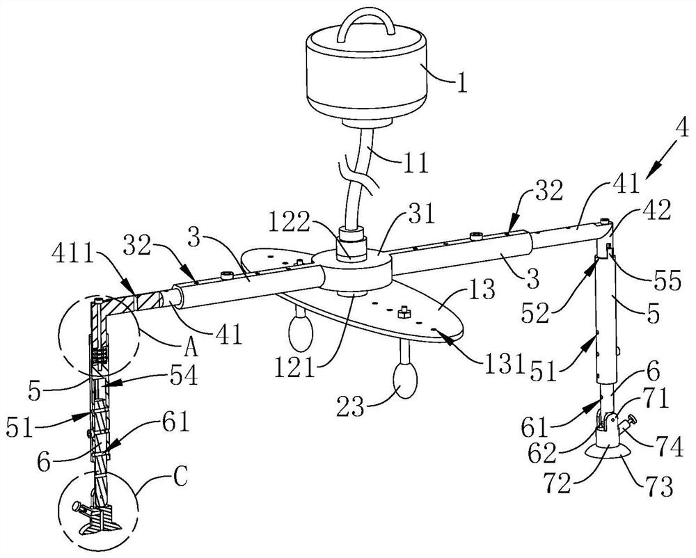
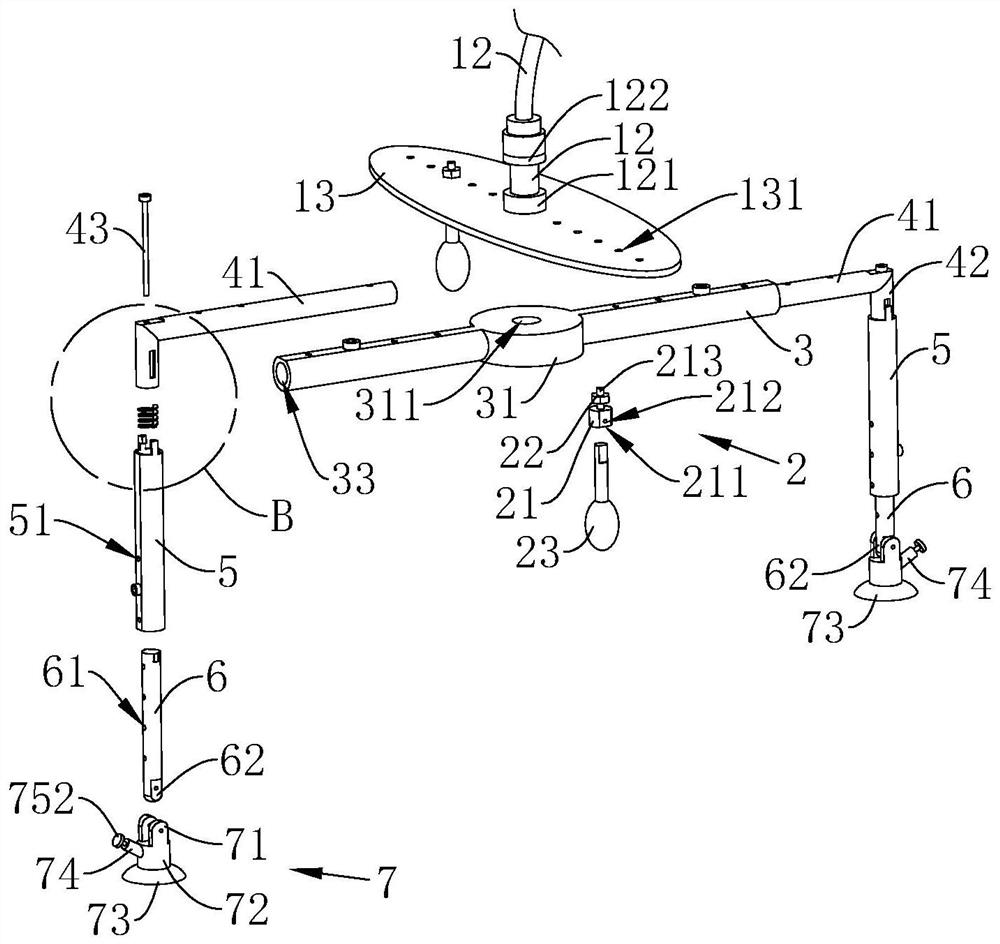
[0031] refer to Figure 1 to Figure 6 As shown, a pressure compensation device for a grinding machine includes a clamping head 2 and a driving motor 1 coaxially rotating with a driving rope 11. The end of the driving rope 11 away from the driving motor 1 is fixedly connected with a rotating head 12, and the rotating head 12 is away from The end of the driving rope 11 is fixedly connected with a rotating plate 13, and the r...


PUM


Abstract

The invention discloses a pressure compensation device of a grinding machine. The pressure compensation device comprises a clamping head and a driving motor which is coaxially provided with a driving rope in a rotating mode, the driving rope is fixedly connected with a rotating head, the rotating head is fixedly connected with a rotating plate, the rotating plate is provided with a plurality of connecting holes in a penetrating mode, the clamping head is detachably connected with the connecting holes through connecting pieces, a rotating head is rotatably connected with a fixing rod in an inserted mode, L-shaped rods are detachably connected to the two ends of the fixing rod, straight rods are arranged at the tail ends, away from the fixing rod, of the L-shaped rods, straight grooves allowing the tail ends of the L-shaped rods to be inserted are formed in one ends of the straight rods, springs are arranged in the straight grooves, the two ends of each springs are fixedly connected with the L-shaped rods and the inner bottom faces of the straight grooves, the two ends of each spring are respectively connected with positive and negative pole input ends of a power supply circuit, and the tail ends, away from the L-shaped rods, of the straight rods are movably connected with an adsorption assembly. By the adoption of the arrangement, polishing and grinding can be carried out on the surface of a workpiece automatically, specified pressure compensation is given according to needs, and therefore the beneficial effects that the working efficiency can be improved, and the labor cost can be saved are achieved.

Description

technical field [0001] The invention relates to the technical field of grinder structures, in particular to a pressure compensation device for a grinder and a method for using the same. Background technique [0002] The full name of the grinding machine is a reciprocating polishing grinding machine, also called a file grinding machine, which is widely used in finishing and surface polishing in the mold industry. The existing grinding machine comprises a driving motor coaxially rotating and provided with a driving rope, the end of the driving rope far away from the driving motor is connected with a chucking head, and the mounting joint is detachably connected with a grinding head. When using a grinding machine to polish and polish mold parts, the grinding head of the corresponding specification will be installed on the chuck at the end of the driving rope, and then the drive motor power will be turned on to polish the surface of the mold parts by manual operation. polished. ...

Claims


Application Information

Patent Timeline
Patent Type & Authority Applications(China)
IPC IPC(8): B24B1/00B24B41/04B24B41/06B24B47/12B24B47/20B24B47/22B24B49/00
CPCB24B1/00B24B41/04B24B41/06B24B47/12B24B47/20B24B47/22B24B49/00
Inventor 魏勇
Owner 广州科源数控科技有限公司
Why Eureka
Try Eureka