


Quick Research
Generate reliable direction feasibility study reports for your R&D in just a few steps.

Technical Q&A
Discover and master advanced knowledge NOW. Basics, ideas, possibilities, all at once.

Find Solutions
As an expert in R&D theories, this can generate solutions to your technical problems instantly.

Evaluate Feasibility
Analyze your overall solution with one click, know your potential R&D risks in advance.

Monitor Landscape
Get weekly tech updates, stay abreast of the latest tech innovations and key insights.
Liquid crystal panel and liquid crystal display
A liquid crystal panel and substrate technology, which is applied to static indicators, instruments, antennas, etc., can solve the problems of unstable assembly of the handwriting input board and the liquid crystal display, increase the thickness of the liquid crystal display, and reduce the input accuracy, so as to avoid errors and meet the requirements of lightness and thinness. requirements, improve accuracy and reliability
- Summary
- Abstract
- Description
- Claims
- Application Information
AI Technical Summary
Problems solved by technology
Method used
Image

Examples
no. 1 example
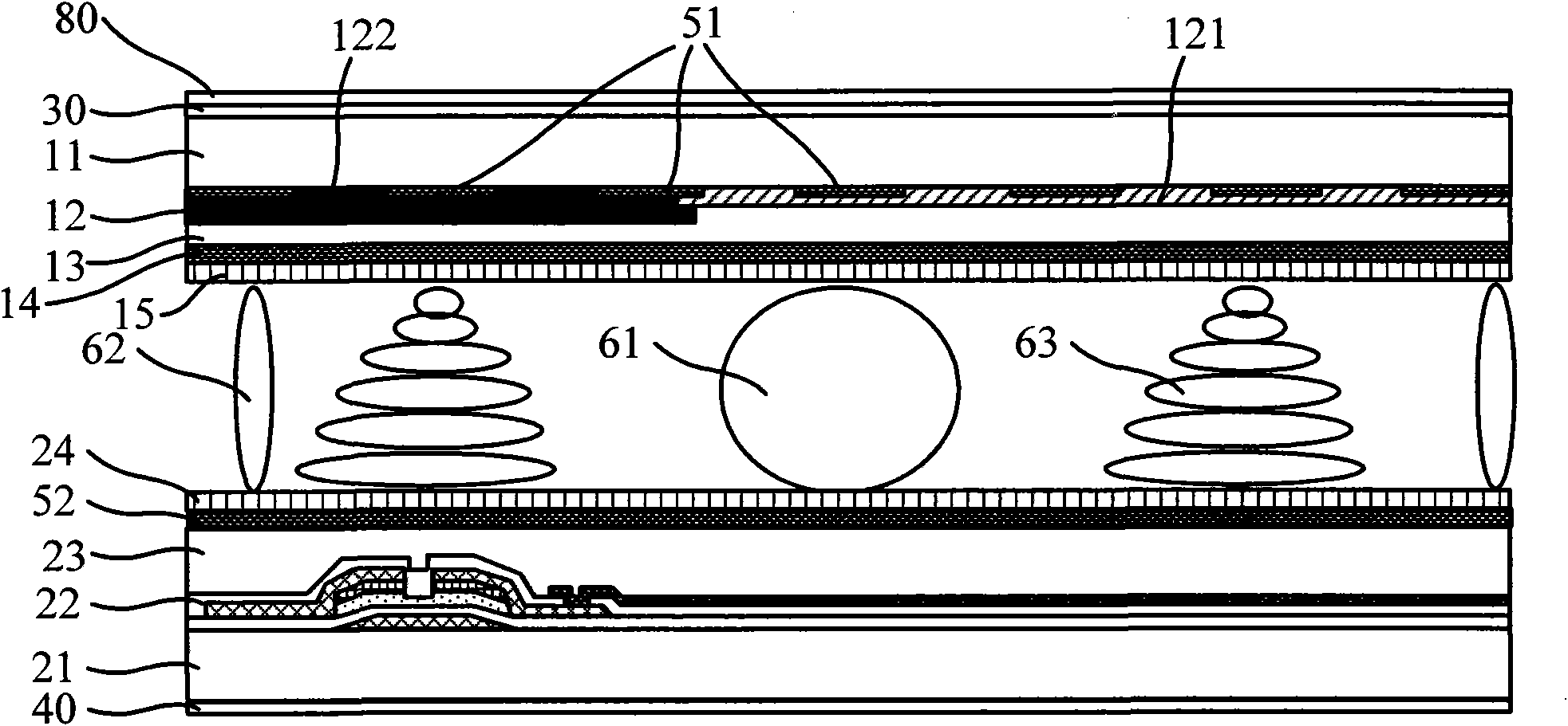
[0034] figure 1 It is a partial side view structure diagram of the liquid crystal panel provided by the first embodiment of the present invention. The plane of the liquid crystal panel is usually divided into a plurality of pixel units. This embodiment takes a typical thin film transistor liquid crystal display as an example for illustration, as shown in figure 1 Shown is the structure of a pixel unit in a liquid crystal panel.
[0035] A typical multi-film layer structure on a color filter substrate starts from the side adjacent to the first base substrate 11, and at least sequentially includes a color resin and a black matrix layer 12, a first protective layer 13, a common electrode layer 14 and a first alignment layer. Membrane 15. The color resin and black matrix layer 12 includes a color filter resin 121 and a black matrix 122 , and the black matrix 122 is arranged between the color filter resins 121 at intervals. The first protection layer 13 is generally made of an o...
no. 2 example
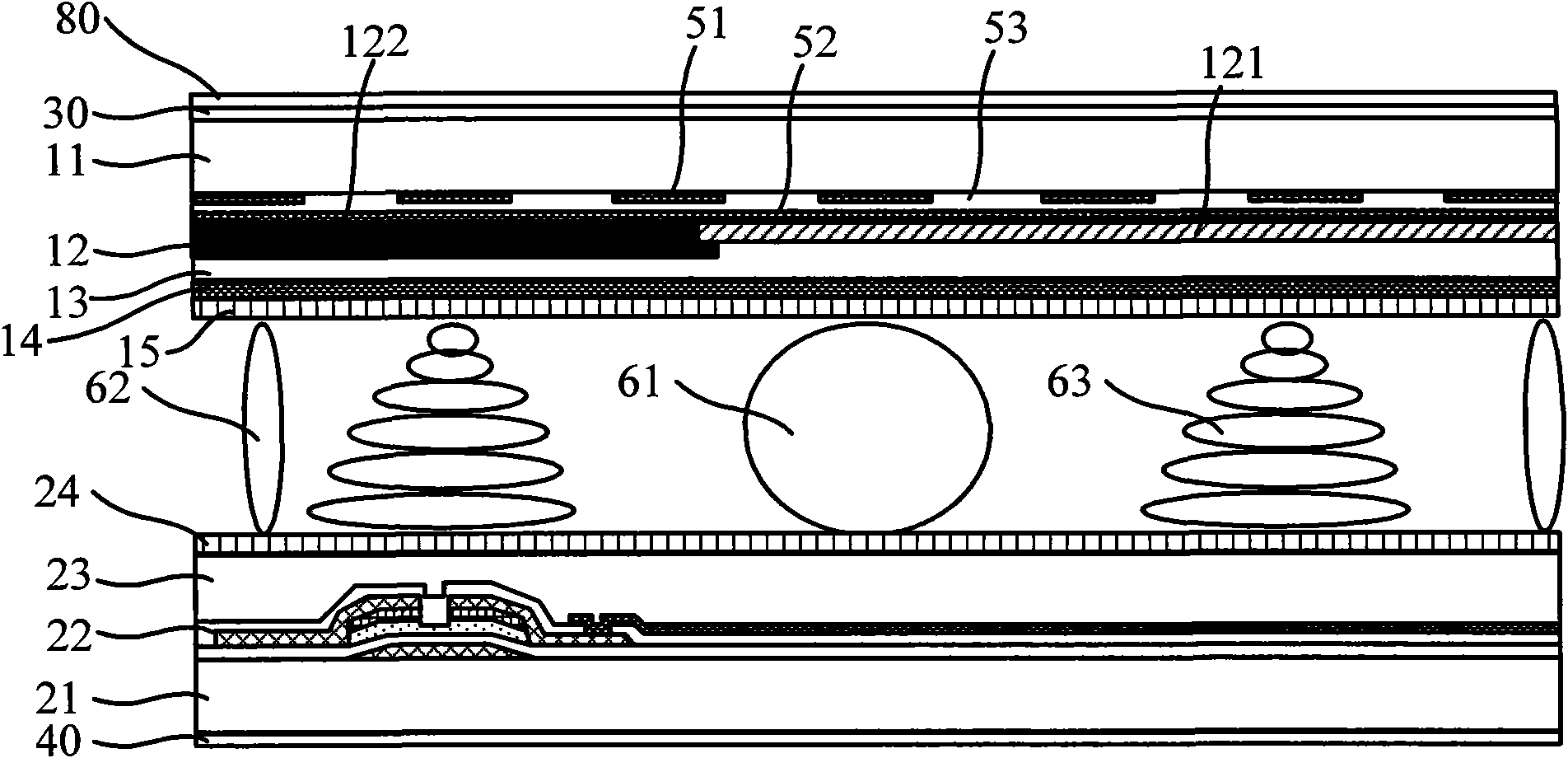
[0048] In the second embodiment of the present invention, the structure of the liquid crystal panel is basically the same as that of the first embodiment. The antenna array includes a first direction wire and a second direction wire perpendicular to each other. The difference is that the first direction wire and the second direction wire cover There is an insulating transparent film layer, that is, when the first direction wire and the second direction wire are formed into the liquid crystal panel, an insulating transparent film layer can be provided on both sides of the first direction wire and the second direction wire respectively, so as to ensure that the first direction wire And the insulation of the second direction wire and the LCD panel.
[0049] In this embodiment, an inner insulating layer 53 may be formed between the first-direction wire 51 and the second-direction wire 52 , so that the first-direction wire 51 and the second-direction wire 52 are kept insulated first...
no. 3 example
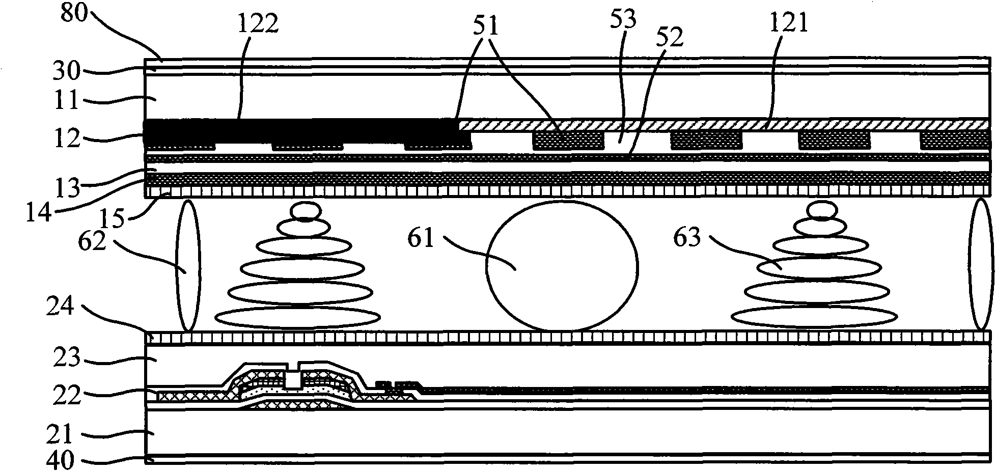
[0055] In the third embodiment of the present invention, the structure of the liquid crystal panel is basically the same as that of the first embodiment, and the antenna array includes a first direction wire and a second direction wire perpendicular to each other, the difference lies in: the first direction wire and / or the second direction wire The top is covered with an outer interval insulating layer, so as to ensure the insulation between the first direction wire and the second direction wire and the conductive material in the liquid crystal panel.
[0056] With the above technical solution, the first direction wire and the second direction wire can be arranged at any position in the two base substrates of the liquid crystal panel, they can be arranged together and kept insulated by an insulating layer inside, or they can be arranged separately. Still taking the typical color filter substrate and array substrate described in the above-mentioned embodiments as an example for ...
PUM
 Abstract
Description
Claims
Application Information
 - R&D Engineer
- R&D Manager
- IP Professional
- Industry Leading Data Capabilities
- Powerful AI technology
- Patent DNA Extraction
Browse by: Latest US Patents, China's latest patents, Technical Efficacy Thesaurus, Application Domain, Technology Topic, Popular Technical Reports.
© 2024 PatSnap. All rights reserved.Legal|Privacy policy|Modern Slavery Act Transparency Statement|Sitemap|About US| Contact US: help@patsnap.com