Eureka AIR delivers breakthrough ideas for toughest innovation challenges, trusted by R&D personnel around the world.

Mobile focusing optical lens group

A technology of optical lens and lens group, applied in the field of optical lens group, can solve the problem of high power consumption of optical lens group

Pending Publication Date: 2022-03-11
ZHEJIANG SUNNY OPTICAL CO LTD
View PDF0 Cites 1 Cited by
  • Summary
  • Abstract
  • Description
  • Claims
  • Application Information

AI Technical Summary

Problems solved by technology

[0005] The main purpose of the present invention is to provide a mobile focusing optical lens group to solve the problem of high power consumption in the optical lens group in the prior art

Method used


Image

  • Mobile focusing optical lens group
  • Mobile focusing optical lens group
  • Mobile focusing optical lens group

Examples


Embodiment 2

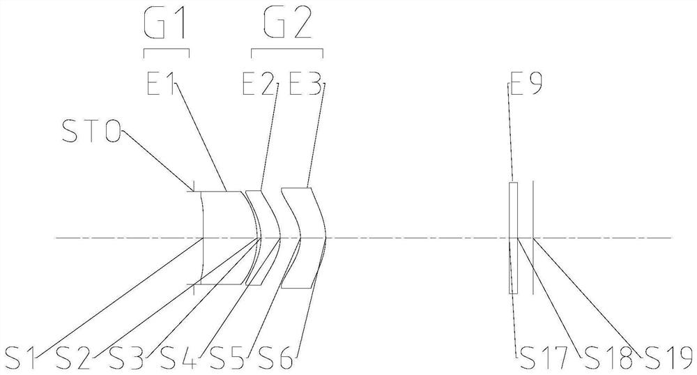
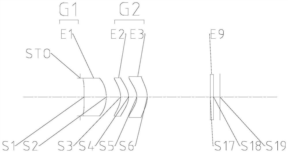
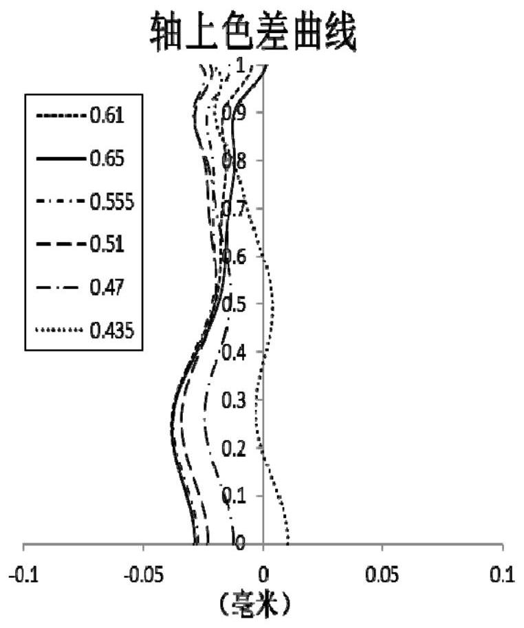
[0097] Such as Figure 1 to Figure 60 As shown, the object side to the image side of the optical lens group that moves the focus includes a first lens group and a second lens group in sequence, the first lens group has a positive refractive power, and the first lens group includes at least one lens with a refractive power lens; the second lens group includes two lenses with optical power; wherein, when the subject moves from infinity to macro distance relative to the optical lens group that moves the focus or when the subject moves relative to the optical lens that moves the focus When the group moves from macro distance to infinity, the second lens group moves on the optical axis to achieve focusing, and the sum ΣCT of the center thicknesses of the first lens of the optical lens group to the last lens of the optical lens group on the optical axis is equal to the first The distance TTL from the object side of a lens to the imaging plane on the optical axis satisfies: 0.2<∑CT / T...


PUM


Abstract

The invention provides an optical lens group for mobile focusing. From the object side to the image side of the optical lens group for moving focusing, the optical lens group sequentially comprises: a first lens group having positive focal power, the first lens group comprising at least one lens having focal power; the second lens group comprises two lenses with focal power; when the object to be shot moves from infinity to macro relative to the optical lens group for mobile focusing or when the object to be shot moves from macro to infinity relative to the optical lens group for mobile focusing, the second lens group moves on the optical axis to realize focusing. When the optical lens group is located at the close-shooting position and the optical lens group is located at the far-shooting position, the interval difference quantity T of the first lens group and the second lens group on the optical axis and the distance TTL from the object side surface of the first lens of the optical lens group to the imaging surface of the optical lens group on the optical axis meet the following condition: T / TTLlt; and 0.25%. According to the invention, the problem of high power consumption of an optical lens group in the prior art is solved.

Description

technical field [0001] The invention relates to the technical field of optical imaging equipment, in particular to an optical lens group for moving focus. Background technique [0002] As portable electronic products become thinner and lighter, the size of each internal part of the product also needs to be reduced, especially in the volume of the camera lens module. Generally speaking, due to space constraints, it is difficult for miniaturized lenses to meet the needs of both telephoto and close-up photography. [0003] In addition, for a camera lens with a focus and focus function, the focus and focus method can be processed by software, such as the extended depth of field technology, using the color of the light shape with the best current distance as the main axis light, and then digitally simulating to achieve the focus effect; Alternatively, the voice coil motor can be used to change the relative distance between the overall camera lens and the image sensor to achieve ...

Claims


Application Information

Patent Timeline
IPC IPC(8): G02B7/10
CPCG02B7/10
Inventor 徐胡伟张晓彬闻人建科戴付建赵烈烽
Owner ZHEJIANG SUNNY OPTICAL CO LTD
Why Eureka
Eureka Blog
Learn More